Reliable carbon powder level measurement starts long before the instrument is powered on. The position of the radar level sensor, the direction of the beam, the location of the filling inlet, the shape of the powder surface, and the internal structure of the silo can all influence measurement stability.
Carbon powder is not a flat, stable target. During filling, the material may form a cone below the inlet. During discharge, a depression may develop above the outlet. The surface can also shift, collapse, or build up unevenly along the wall.
For this reason, installing a radar sensor in the geometric center of a silo does not automatically guarantee the best result.
A good installation should allow the radar beam to see a representative part of the material surface while avoiding the falling product stream, silo walls, ladders, supports, and other fixed objects.
This guide explains the main points to consider when installing a radar level sensor on a carbon powder silo.

Why Installation Position Matters
A radar level sensor measures the distance between its antenna and the material surface.
In a liquid tank, the surface is normally horizontal, so a reading at one point usually represents the overall level reasonably well.
Powder behaves differently.
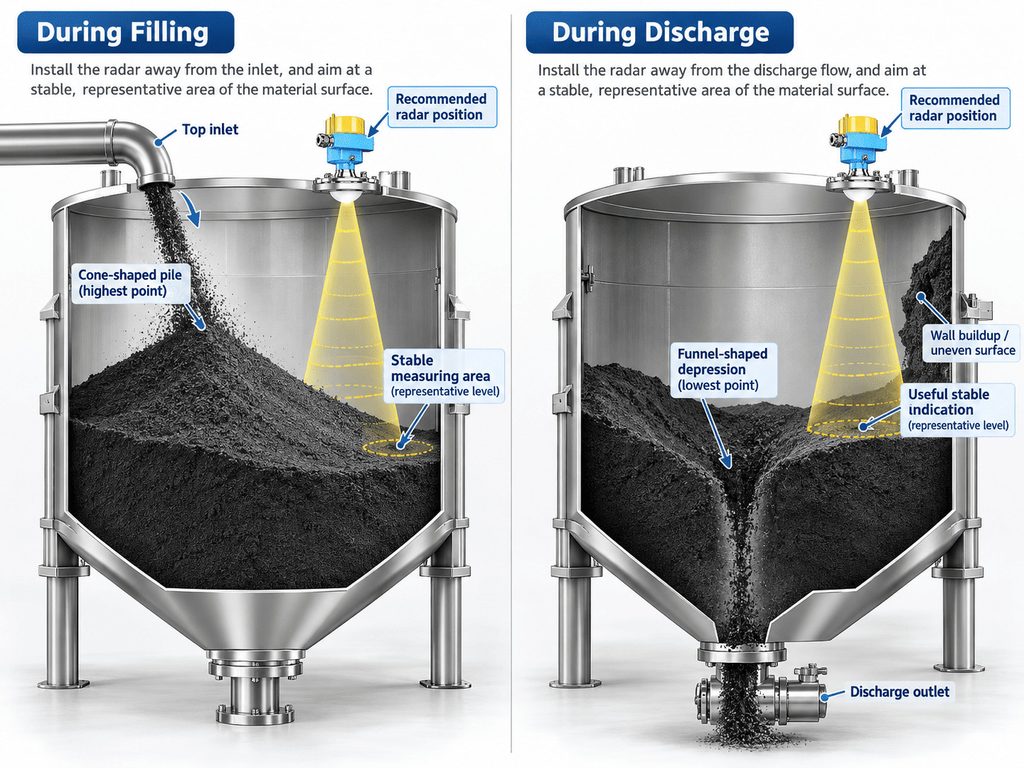
When carbon powder enters through a top inlet, it can create a cone-shaped pile. The highest point may be close to the inlet while other areas remain much lower.
During discharge, powder moves toward the outlet and may create a funnel-shaped depression.
If the material sticks to the wall, bridges, or collapses unevenly, the surface becomes even more irregular.
The goal is therefore not simply to aim at the highest or lowest point. The radar should look at an area that provides a stable and useful indication throughout normal filling and discharge.
That is why the mounting location should be selected according to actual material movement, not only according to the vessel centerline.
Keep the Radar Beam Away From the Filling Stream
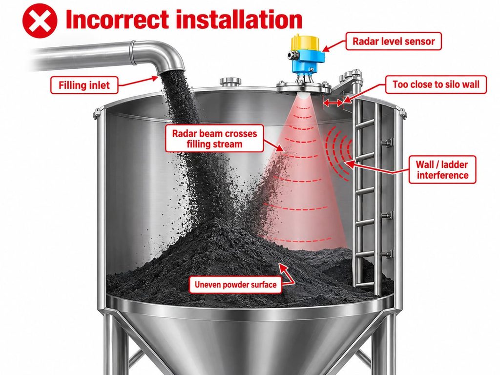
One of the most common installation mistakes is mounting the radar sensor directly above or too close to the filling inlet.
During filling, carbon powder can fall through the radar beam as a dense moving stream.
The instrument may receive strong reflections from the falling material before the signal reaches the stored powder surface. Pneumatic conveying can also create a very dusty environment.
The result may be unstable readings, temporary signal loss, or a displayed level that follows the incoming material rather than the true stored level.
A better approach is to position the sensor so the beam has a clear path to the powder surface without crossing the main filling stream.
Before selecting the mounting point, identify the real trajectory of the incoming material.
Product does not always fall vertically. Angled pipes, pneumatic lines, elbows, deflectors, or distributors can change where the powder lands.
A useful installation drawing should therefore show both the filling path and the radar beam.
Avoid Mounting Too Close to the Silo Wall
Moving the sensor away from the filling stream is important, but moving it too close to the wall can create another problem.
Silo walls may produce unwanted reflections.
The risk increases when the beam also reaches weld seams, reinforcing rings, ladders, platforms, braces, internal pipes, or material buildup on the wall.
There is no universal wall-clearance distance that fits every silo.
The correct position depends on the radar beam angle, antenna design, vessel diameter, installation height, and internal geometry.
Instead, review the complete beam footprint from the sensor down to the lowest expected material level.
The main beam should remain as clear as possible from fixed structures.
A narrow beam can make installation easier in tall or narrow silos because it concentrates the measurement energy into a smaller area. Industrial radar manufacturers similarly emphasize narrow beam angles as an advantage for solids silos and vessels containing internal obstructions.
Even so, careful positioning remains important.
Understand the Beam Angle
A radar beam is not a thin straight line.
It expands with distance.
A location that appears clear near the top of the silo may still allow the beam to intersect a ladder, wall, or support farther down.
This becomes especially important when the silo is tall or narrow.
When reviewing the installation, consider the complete beam cone over the full measuring range.
If the silo contains internal structures, position the sensor so these objects remain outside the main beam whenever possible.
In difficult geometries, an aiming flange or adjustable mounting arrangement may help direct the beam toward a better measurement zone.
This is particularly useful when the silo has an off-center outlet, a narrow diameter, multiple supports, or a strongly sloped powder surface.
Consider Both Filling and Discharge Conditions
A reliable installation should work through the full operating cycle.
During filling, the sensor may see a rising cone.
During storage, the powder may settle.
During discharge, the cone can flatten and then develop into a depression.
Near empty conditions, the radar may begin to see the sloping hopper or outlet area.
A mounting point that performs well at high level may not necessarily be ideal at low level.
Before installation, it is useful to sketch several expected powder profiles:
- High level during filling
- Normal operating level
- Low level during discharge
- Near-empty condition
Then draw the radar beam over each profile.
This simple check helps determine whether the beam will continue to strike a representative material surface as the silo level changes.
Check the Mounting Nozzle and Flange
The mechanical connection can also influence radar performance.
A sensor mounted on a long or narrow nozzle may experience unwanted reflections from the nozzle itself.
If the antenna is recessed too deeply, the nozzle may partially block or disturb the outgoing signal.
The mounting arrangement should therefore follow the requirements of the selected sensor. A clear view into the silo is generally desirable.
The flange should also be mechanically stable and correctly aligned.
If the transmitter is tilted unintentionally, the beam may point toward the wall instead of the intended measurement area.
If an aiming flange is used, document its final direction during commissioning so future maintenance does not accidentally change the alignment.
Avoid Internal Obstacles and False Echoes
Typical silo internals include ladders, reinforcing beams, supports, filling pipes, temperature probes, level switches, extraction equipment, and structural braces.
These objects can create fixed echoes.
The problem may become more noticeable when the true reflection from the powder surface is relatively weak.
The best approach is to keep the main radar beam clear of these structures.
If complete avoidance is impossible, commissioning functions such as echo mapping or false-signal suppression may help the instrument distinguish the real material surface from fixed objects.
However, software should not be used to compensate for poor installation if a better mounting position is available.
A clean beam path remains the preferred starting point.
Plan for Dust and Material Buildup
Carbon powder can generate heavy dust, particularly during pneumatic filling.
Fine particles may also settle around the process connection or antenna area over time.
Non-contact radar has an advantage because no long probe needs to extend into the stored powder. Radar instruments are widely used in dusty bulk-solid applications for this reason.
Even so, the sensor should not be placed where incoming material directly strikes the antenna.
If significant buildup is expected, evaluate whether the selected instrument and mounting arrangement support appropriate anti-buildup measures or air purging.
The mounting area should also be included in routine inspection plans.
Long-term reliability depends not only on how well the sensor works on the first day, but also on how the installation behaves after weeks or months of dusty operation.
Commission the Sensor Under Real Process Conditions
A stable reading in an empty silo is not enough to prove that the installation is correct.
The radar should be checked during real filling and discharge.
Observe what happens when filling starts, when the powder surface rises past internal structures, and when the silo approaches low level.
If the transmitter provides an echo curve or diagnostic display, record a baseline during commissioning.
This can later help identify changes caused by buildup, process modifications, or new interference.
Configure key parameters such as empty distance, full distance, damping, product characteristics, and false-echo handling for the real application rather than relying blindly on default settings.
For critical overfill protection, the plant risk assessment may also call for an independent point level switch in addition to continuous radar measurement.
Carbon Powder Silo Radar Installation Checklist
Before approving the installation, verify that the radar beam does not cross the main filling stream and does not unnecessarily approach the silo wall.
Confirm that ladders, braces, pipes, and other structures are outside the main beam where possible.
Check that the sensor can see a useful powder surface at both high and low levels.
Make sure the mounting nozzle and flange are suitable for the antenna, and confirm the direction of any aiming flange.
The selected measuring range should cover the full distance to the lowest required level.
Electrical, environmental, and hazardous-area requirements should also be verified for the installation site.
Finally, include real filling and discharge tests in the commissioning plan.
Final Thoughts
Installing a carbon powder silo radar level sensor is not simply a matter of choosing an available flange on top of the vessel.
The sensor must measure a surface that changes shape throughout the process.
The filling stream, discharge funnel, wall, structural obstacles, dust, and buildup can all influence the echo environment.
A successful installation starts with understanding how the powder moves inside the silo.
Keep the radar beam away from the filling stream and fixed obstacles, consider the complete beam angle, choose a representative measurement area, and verify performance under actual operating conditions.
When the mechanical installation and commissioning are both handled correctly, radar can provide stable, non-contact carbon powder level measurement while reducing unnecessary manual checks and improving visibility into silo inventory.