
In cement, building materials, grain processing, chemicals, mining, and power generation, the surface of stored solids is rarely flat. Material entering a silo may form a cone-shaped pile, while discharging material may create a central depression or an uneven slope. If a radar level meter is installed in a fixed vertical position, its beam may not reach the most representative part of the material surface. The result can be a weak echo, unstable readings, false targets, or even temporary signal loss.
An adjustable process connection provides a practical solution. By changing the antenna angle after the instrument has been mounted, engineers can direct the radar beam toward a stronger and more stable reflection area. This is the main reason a universal flange is often selected for radar instruments used on powder, granule, and lump-material silos.
Although it may appear to be a simple mechanical accessory, the flange has a direct effect on signal quality. Correct alignment can improve echo strength, reduce interference from internal structures, and make commissioning easier. However, reliable measurement still depends on proper instrument selection, installation position, process conditions, and parameter configuration.
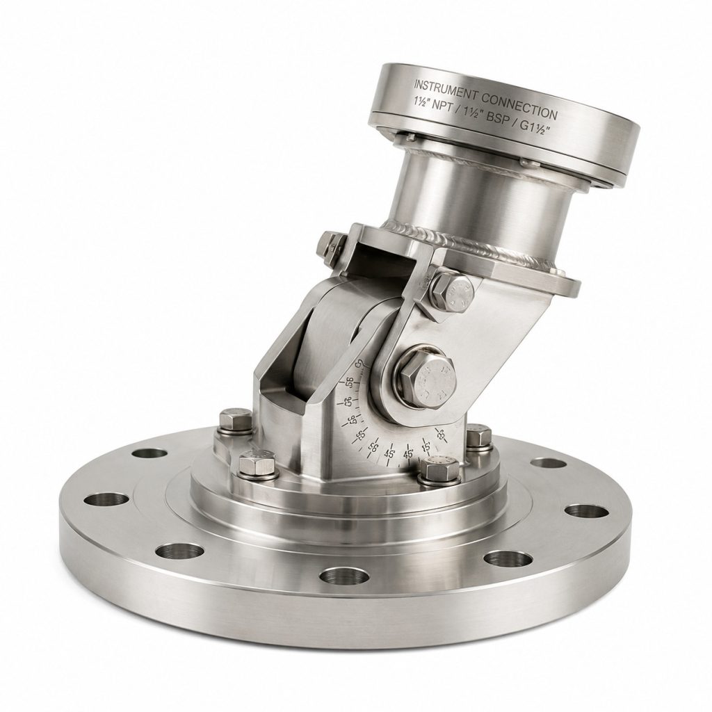
What Is a Universal Flange?
A conventional fixed flange connects a level instrument to a tank or silo, but it normally offers little or no control over antenna direction after installation. If the mounting nozzle is off-center, the roof is inclined, or the material surface has a permanent slope, a fixed connection may not provide the best beam path.
A universal flange adds an angular adjustment function to the process connection. Depending on the design, it may use a spherical joint, a rotating bracket, or another adjustable mechanism. The installer can tilt the radar antenna within a specified range and then lock it securely in position.
Its main functions are to:
- connect the level meter to the vessel or silo;
- adjust the direction of the radar antenna;
- maintain mechanical stability and process sealing;
- help the radar beam avoid internal obstacles;
- guide the beam toward a useful measurement area.
The word “universal” does not mean unlimited rotation. Every design has a defined adjustment range, pressure rating, temperature limit, sealing structure, and mechanical load capacity. These values must be checked against the manufacturer’s technical documentation.
Why Adjustable Alignment Matters in Solid Level Measurement
A radar level meter sends electromagnetic waves toward the product surface and receives the reflected signal. The instrument calculates the distance between the antenna and the material by analyzing the transmitted and returned signals. It then converts that distance into a level value.
Liquids usually form a relatively even surface when calm, so a vertically mounted radar can often obtain a clear reflection. Bulk solids behave differently. Their surface shape changes according to the filling point, discharge position, angle of repose, particle size, flowability, moisture content, and silo geometry.
Typical conditions include:
- a high pile below the filling inlet;
- one side of the silo remaining higher than the other;
- a funnel-shaped depression above the outlet;
- loose powder with an irregular surface;
- large particles producing scattered reflections;
- shifting material profiles during filling and emptying.
When a radar beam hits a steep or uneven surface, part of the energy may be reflected away from the antenna. The useful echo becomes weaker, while echoes from walls, ladders, beams, or filling pipes may become more prominent.
An adjustable mounting angle helps solve this problem physically. Instead of relying only on signal-processing settings, the installer can aim the antenna toward an area that produces a stronger and more representative echo.
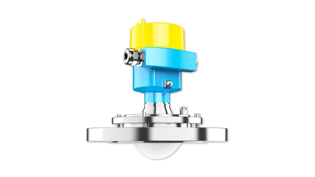
Key Benefits in Radar Level Applications
1. Better Beam-to-Surface Alignment
The most direct benefit is improved alignment between the radar beam and the product surface. In silos with cone-shaped piles, sloping material, or off-center filling, a small antenna adjustment can significantly improve the reflected signal.
The goal is not necessarily to make the beam perfectly perpendicular to the entire surface. In most applications, that is impossible because the surface changes continuously. The objective is to cover a stable and representative area with good reflection characteristics.
2. Compensation for an Imperfect Mounting Position
Many existing silos were built without an ideal opening for a modern radar level transmitter. The available nozzle may be too close to the wall, away from the center, or positioned near internal equipment.
Creating a new opening may require shutdown, hot-work permits, structural evaluation, high-level access, and additional fabrication. An adjustable connection can compensate for a limited amount of positional error by redirecting the antenna toward a better target area.
This approach has limits. If the beam path is blocked by a large crossbeam, filling chute, ladder, or continuous material stream, changing the angle alone may not be enough. Relocating the instrument may still be necessary.
3. Reduced Interference from Internal Structures
Large silos often contain reinforcement rings, support beams, ladders, filling pipes, dust-removal lines, or other metal components. These objects can create strong fixed echoes.
By adjusting the antenna direction, the beam can sometimes be moved away from these obstacles. This improves the separation between the true material echo and unwanted reflections. False-echo suppression or mapping functions can then be used to handle the remaining stationary interference.
Mechanical alignment and software filtering should be treated as complementary measures. Signal processing is most effective after the antenna has been installed in a sensible position. Universal Flange
4. Easier Commissioning and Maintenance
A fixed process connection requires the mounting nozzle and roof angle to be accurate before the instrument is installed. An adjustable design gives commissioning engineers more flexibility.
After installation, they can observe the live echo curve, signal strength, interference positions, and level trend. Small changes can then be made to the antenna angle until a stable target is obtained. This is generally more convenient than repeatedly removing the instrument, fabricating a sloped nozzle, or cutting a new opening.
Which Level Instruments Commonly Use This Design?
The universal flange is most commonly associated with non-contact radar level meters used for continuous measurement of powders, granules, and bulk solids. Universal Flange
Typical applications include:
- cement, fly ash, and clinker silos;
- coal bunkers and ash silos in power plants;
- wheat, corn, feed, and grain storage;
- plastic pellet and chemical powder vessels;
- ore, coke, and additive bins;
- mineral and metallurgical storage;
- powder-material silos in battery and new-energy production.
Standard threaded or fixed-flange mounting is often sufficient for ordinary liquid tanks because the liquid surface is usually level. An adjustable arrangement may still be useful when the tank roof is inclined, the nozzle is off-center, the vessel contains internal obstructions, or the sensor must avoid an agitator or inlet stream.
Example: Jiwei JWrada Radar Level Meters
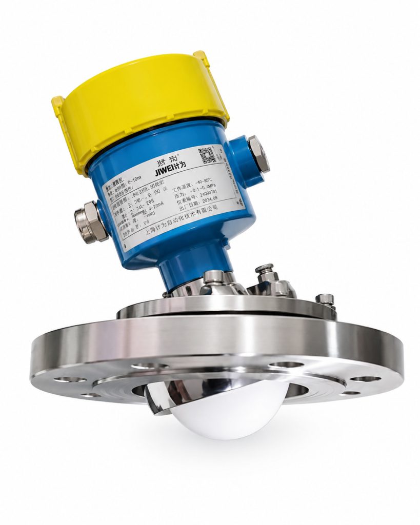
According to Jiwei’s public product information, the JWrada®-34 radar level meter uses 80 GHz millimeter-wave radar technology and can be supplied with a purging system and an adjustable process connection for demanding solid-level applications. Its lens antenna is designed for measurement in powders, bulk solids, dust, and vapor conditions, including some low-dielectric materials.
High-frequency radar normally provides a narrow and concentrated beam. This helps reduce reflections from vessel walls and internal structures. However, a narrow beam also makes the installation direction more important. If the antenna points away from the useful material surface, the advantages of a focused beam may not be fully realized.
In this situation, the universal flange works together with the antenna design, echo-processing algorithm, and commissioning procedure. The mechanical connection first aims the beam toward a suitable region. Echo mapping, false-target recognition, and dynamic tracking can then be used to manage the remaining interference.
Jiwei’s installation information also indicates that solid-level instruments should be mounted at a suitable distance from the vessel wall. Where an adjustable bracket is used, the inclination can be changed by rotating the support structure. The best angle depends on measuring distance, nozzle position, silo geometry, and the expected material profile.
Some published examples show a maximum bracket inclination of approximately 10 degrees, although the actual limit must be confirmed for the selected model.
This illustrates an important point: antenna alignment should not be based on visual judgment alone. It should be determined using vessel dimensions, offset distance, target area, beam angle, and the measured echo curve.
Recommended Installation Procedure
Choose a Suitable Mounting Location
A radar instrument should not normally be installed directly above the filling stream. Falling material can create a strong moving reflection and may prevent the sensor from detecting the actual stored level.
The mounting point should also avoid ladders, reinforcement beams, filling pipes, braces, and other large reflecting structures. Jiwei’s published guidance for certain solid applications recommends keeping the instrument approximately 200 mm or more from the vessel wall.
The required clearance depends on the silo diameter, antenna type, beam angle, nozzle design, and instrument model. The technical manual for the selected product should always take priority.
Identify the Expected Material Profile
Before installation, determine where the material enters, where it leaves, and how the surface normally develops during operation.
If filling occurs mainly on one side, the antenna should usually be directed toward a stable and representative area rather than simply toward the highest point. Measuring only the top of the pile may give a misleading indication of average inventory and can cause large fluctuations as the pile moves.
The expected surface profile should be evaluated under both filling and discharging conditions. A direction that works well during filling may not necessarily provide the best measurement after a large quantity of material has been discharged.
Adjust the Angle Using the Echo Curve
After mechanical installation, examine the echo curve at different operating stages whenever possible, such as an empty silo, low level, normal level, filling, and discharging.
If the true material echo is weak or a false reflection is too strong, adjust the flange angle in small increments. Check the echo after each movement. Avoid making a large change at once because the beam may shift toward a wall or another obstacle.
When the best direction has been found, tighten all fasteners to the specified torque. A loose assembly may gradually move because of vibration, wind load, thermal expansion, or mechanical shock.
The adjustment should also be recorded during commissioning. Documenting the final angle and echo condition makes future maintenance and troubleshooting much easier.
Perform False-Echo Mapping
If the silo contains fixed internal obstacles, false-echo mapping can record their reflection positions and reduce their influence on level evaluation.
This function should be used after the physical installation has been optimized. It cannot compensate for a severely incorrect mounting location, a beam pointed directly at a large steel structure, or an antenna that does not cover the product surface.
False-echo mapping should also be carried out under suitable process conditions. If possible, it is best performed when the actual material level is known and the unwanted reflections can be clearly distinguished from the real product echo.
Important Selection Factors
When specifying a universal flange for a level meter, do not focus only on the available tilt angle.
First, confirm the flange standard, nominal size, pressure class, sealing face, bolt pattern, and nozzle compatibility. The process connection must match the existing vessel interface.
Second, calculate the approximate angle required from the nozzle offset and silo height. The permitted adjustment range must be sufficient without placing the joint near its mechanical limit.
Third, check temperature, pressure, material compatibility, and sealing performance. High temperature, corrosive media, elevated pressure, and hazardous dust may require special metals, gaskets, seals, or certified designs.
Fourth, evaluate the radar frequency, beam angle, antenna diameter, measuring range, and sensitivity to low-dielectric materials. Adjustable alignment solves a directional problem; it does not determine whether the radar itself is suitable for heavy dust, condensation, buildup, long measuring ranges, or weak-reflection products.
Finally, consider purging, ingress protection, and explosion protection. In dusty applications, an air-purge arrangement may reduce buildup on the antenna. Hazardous areas require equipment with approvals appropriate for the site classification.
The Relationship Between Radar Frequency and Installation Direction
Modern radar level instruments are available in several operating frequencies. Higher-frequency instruments, including many 80 GHz models, generally produce a narrower beam than lower-frequency devices with a similar antenna size.
A narrow beam can provide several advantages in solid-level applications. It can pass through smaller openings, reduce the area exposed to internal obstacles, and focus more energy on a specific section of the material surface.
However, a focused beam also makes correct aiming more important. A wide beam may still cover part of the product surface when the instrument is slightly misaligned, while a narrow beam may completely miss the preferred target area.
For this reason, the universal flange is especially useful when a high-frequency radar is installed on a tall silo, an off-center nozzle, or a vessel with an uneven material profile.
The radar frequency should not be selected only according to beam width. Product reflectivity, dust, buildup, moisture, temperature, pressure, antenna design, and measuring range must also be considered.
Applications in Different Industries
Cement and Building Materials
Cement plants often need to measure cement powder, fly ash, limestone powder, clinker, and other bulk materials. These products may generate heavy dust and form steep piles during filling.
An adjustable radar mounting can help direct the beam away from the filling stream and toward a more stable surface. Purging may also be used to reduce dust accumulation on the antenna.
Grain and Feed Processing
Grain, corn, wheat, animal feed, and similar products can form large cone-shaped piles. Their surface profile changes as material enters or leaves the silo.
Correct beam alignment helps the sensor follow these changing conditions and reduces the risk of measuring an unrepresentative high point near the filling inlet.
Power Generation
Coal bunkers, fly-ash silos, and desulfurization material vessels are often dusty and contain irregular solids. Internal supports and filling equipment may also create false reflections.
A properly aimed radar beam, combined with false-echo suppression, can improve continuous level monitoring in these demanding applications.
Chemicals and Plastics
Chemical powders and plastic pellets may have relatively low dielectric properties, making the reflected radar signal weaker than that of water or conductive liquids.
The antenna direction becomes especially important when measuring weak-reflection materials. A strong mechanical installation and suitable radar frequency are both required.
Mining and Metallurgy
Ore, coke, crushed stone, and other large solids produce uneven surfaces and scattered echoes. The material may also cause impact, vibration, and abrasion around the process connection.
In these applications, the mechanical strength of the mounting assembly is as important as its adjustment capability.
Common Installation Mistakes
One mistake is assuming that the antenna can be tilted in any direction once an adjustable connection is installed. Excessive inclination may direct the beam toward the vessel wall, outlet cone, or another source of interference.
Another mistake is aiming only at the highest point of a static pile. Material distribution changes during operation, so the selected direction should remain useful during both filling and discharging.
A third mistake is ignoring process sealing. An articulating connection contains movable parts and must still meet the required pressure, temperature, and leakage limits. An ordinary mechanical adapter should not be used as a substitute for a properly engineered process fitting.
A fourth mistake is failing to lock the assembly after adjustment. Silo roofs may experience vibration, wind, equipment movement, and thermal expansion. Inadequate tightening can allow the antenna direction to drift over time.
A fifth mistake is blaming every unstable reading on the mounting angle. Poor performance may also be caused by low dielectric properties, antenna buildup, condensation, incorrect parameters, power-supply problems, grounding issues, or electromagnetic interference.
Troubleshooting should therefore cover the complete measurement system rather than a single component.
Maintenance Recommendations
The mounting assembly should be inspected during routine maintenance. Check that the locking bolts remain tight and that the antenna direction has not changed.
Inspect the sealing components for wear, corrosion, cracking, or leakage. In dusty environments, examine the antenna surface for buildup and confirm that any purging system is operating correctly.
Measurement trends should also be reviewed. A gradual increase in signal noise or a reduction in echo strength may indicate antenna contamination, mechanical movement, or a change in process conditions.
After major maintenance, silo modification, or replacement of filling equipment, the radar echo curve should be checked again. Changes inside the vessel can create new interference reflections even when the level meter itself has not been moved.
Conclusion
An adjustable flange may look like a minor accessory, but it can have a major influence on radar signal quality. In applications involving powders, granules, uneven solids, cone-shaped piles, off-center filling, and tall silos, proper antenna alignment helps compensate for nozzle position, avoid obstacles, and strengthen the true material echo.
It is not a solution for every measurement problem. Reliable results still require the correct radar technology, a suitable mounting location, careful angle adjustment, echo verification, proper configuration, and routine maintenance.
When selecting a radar level meter, users should provide the supplier with the material name, dielectric properties, silo height and diameter, filling and discharge positions, expected surface profile, dust conditions, process temperature and pressure, and hazardous-area requirements.
Matching the instrument, process connection, and application conditions is the best way to achieve stable non-contact level measurement with low maintenance and long-term reliability.
Frequently Asked Questions
Is a universal flange used only with radar level meters?
It is most commonly used with radar instruments for solid level measurement. Similar adjustable structures may also be used with other non-contact sensors, but suitability depends on the measurement principle and the manufacturer’s design.
Is a larger adjustment angle always better?
No. The correct angle is the one that allows the beam to reach a stable and representative material surface. Too much inclination can increase reflections from walls or internal structures.
Is false-echo mapping still necessary after angle adjustment?
In many complex silos, yes. Mechanical adjustment improves the physical beam path, while false-echo mapping helps suppress remaining fixed reflections. The two methods work best when used together.
Do liquid level applications require this type of connection?
Most tanks with a calm, level liquid surface do not. It may still be useful when the nozzle is inclined or off-center, when internal obstructions are present, or when the beam must avoid an inlet or agitator.
Which industries commonly use adjustable radar mounting?
Common users include cement, power generation, grain and feed processing, chemicals, mining, metallurgy, building materials, plastics, and new-energy powder manufacturing.

