
In normal saline production, level control in mixing tanks, storage tanks, buffer vessels, and transfer pipelines directly affects batching continuity, pump safety, and the stable operation of downstream filling processes.
If the liquid level in a mixing tank becomes excessively high, an overflow may occur. This not only causes product loss but may also increase cleaning requirements within the cleanroom and create additional pressure on batch management. If the liquid level becomes too low while the transfer pump continues running, the pump may run dry, the flow may be interrupted, and downstream equipment may suffer from insufficient material supply.
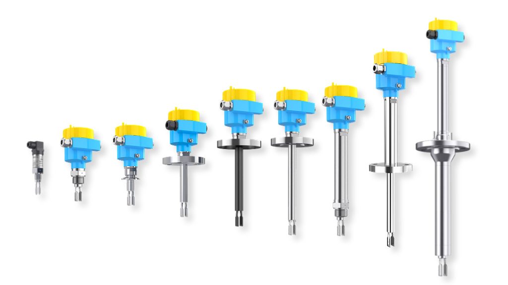
To address these typical requirements on a pharmaceutical normal saline production line, Jiwei Ring-11 sanitary tuning fork level switches were installed at the high- and low-level positions of the mixing tank. An additional switch was installed in the discharge pipeline to detect the presence or absence of liquid.
The switch signals were connected to the programmable logic controller, or PLC, and interlocked with the inlet valve, transfer pump, and audible and visual alarm system. This configuration created a straightforward, responsive, and easy-to-maintain point-level control solution.
1. Why Normal Saline Production Requires Reliable Level Switches
Normal saline generally refers to a 0.9% sodium chloride solution. Publicly available documentation from China’s National Medical Products Administration also describes 0.9% sodium chloride injection as a product used for fluid and electrolyte replacement and other related clinical purposes.
From a level-measurement perspective, normal saline is a free-flowing aqueous solution. Its main measurement challenges do not come from high viscosity. Instead, they arise from the combined sanitary, cleaning, batch-control, and automated interlocking requirements of pharmaceutical production.
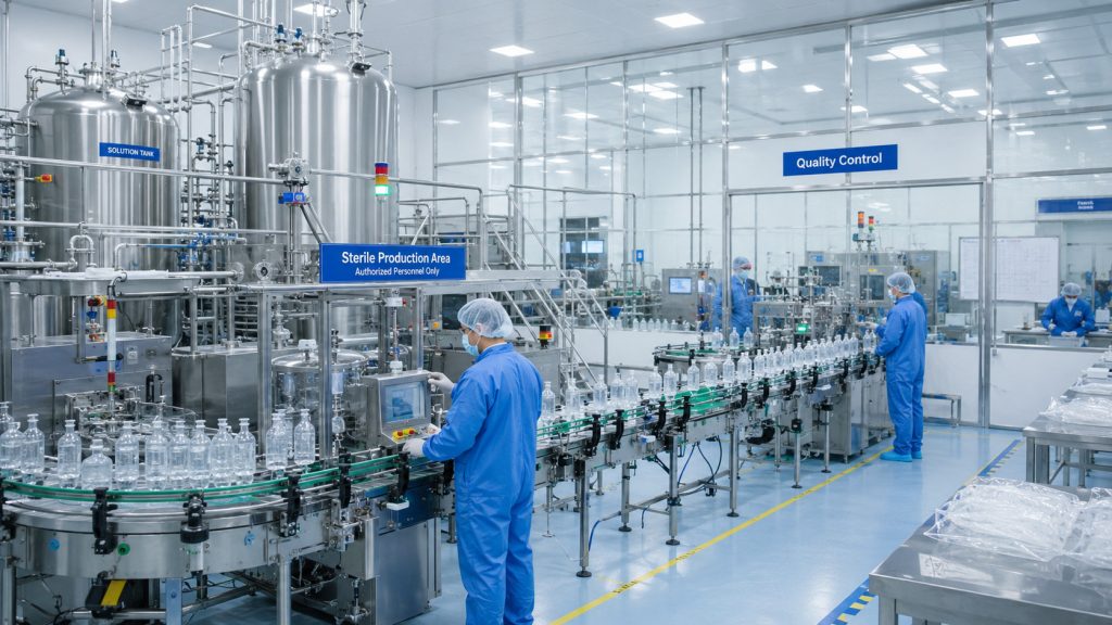
A typical normal saline production line may include purified or injectable water supply, sodium chloride feeding, solution preparation, circulation and mixing, filtration, temporary storage, and filling.
Within these processes, point-level switches commonly perform several essential functions.
First, when the mixing tank reaches its preset high-level position, the switch sends a signal to close the water inlet valve or stop upstream feeding equipment, preventing further filling and possible overflow.
Second, when the liquid level in the mixing or storage tank falls to the preset low-level position, the switch stops the transfer pump and protects it against dry running.
Third, a level switch may determine whether a discharge pipeline is filled with liquid, providing a permissive signal for filtration, transfer, or filling equipment.
Fourth, the switch may serve as an independent high-high or low-low protection point in addition to a continuous level transmitter, thereby improving the reliability of the overall level-control system.
Fifth, during cleaning, draining, or batch changeover, the level switch can provide the PLC with a clear “liquid present” or “no liquid” status.
Consequently, level measurement in normal saline production involves more than simply detecting whether liquid is present. The solution must also support sanitary installation, convenient cleaning, stable switching repeatability, and compatibility with the plant automation system.
2. Project Background and Challenges of the Existing Level-Control System
The pharmaceutical company in this case operated a normal saline preparation and filling line. Its preparation system included stainless-steel mixing tanks, sanitary transfer pipelines, filtration units, temporary storage tanks, and filling equipment.
Before the upgrade, the mixing tank mainly relied on a continuous level signal for process monitoring. Operators manually controlled some filling and transfer operations according to the displayed level trend.
As the plant increased its level of automation, the company decided to add independent point-level protection devices. The purpose was to reduce the risk that a failure or abnormality in a single continuous-measurement signal could affect production.
Four main challenges were identified.
2.1 High-Level Protection Had to Be Independent of the Continuous Measurement Loop
A continuous level transmitter is suitable for displaying changing liquid levels and supporting normal process control. However, the company required a separate high-level switch for protective interlocking.
When the liquid reached the predefined high-level position, the switch needed to send a direct digital signal to the PLC. The PLC would then close the inlet valve and activate an alarm.
Separating process measurement from limit protection made the control philosophy clearer and provided an additional layer of protection.
2.2 The Transfer Pump Was Exposed to Dry-Running Risk
Normal saline was transferred from the mixing tank to the filtration or filling process. If the tank level became too low, the pump inlet could draw in air.
In less severe cases, this could cause unstable flow. In more serious cases, the pump could continue operating without sufficient liquid.
A low-level switch was therefore required near the bottom of the tank. When the tuning fork was no longer submerged, the switch would immediately change state. The PLC would then stop the transfer pump and prevent it from restarting until safe operating conditions were restored.
2.3 Sanitary Design and Cleaning Requirements Were Strict
A level switch installed in a mixing tank comes into direct contact with the pharmaceutical solution. Its process connection, wetted materials, and surface finish must therefore be suitable for pharmaceutical production.
The instrument should also minimize areas where product residues may accumulate and should support convenient cleaning between production batches.
According to Jiwei’s official product information, the Ring-11 sanitary tuning fork level switch is available with a clamp-type process connection. Its sanitary probe can achieve a surface roughness of Ra below 0.5 μm, making it suitable for level detection in storage tanks, mixing vessels, and pipelines used in food, beverage, and pharmaceutical production.
2.4 Installation Space in the Pipeline Was Limited
The normal saline transfer pipeline was surrounded by valves, filters, and sampling devices. As a result, the space available for instrument installation was limited.
An excessively long probe could interfere with the internal flow pattern and make installation more difficult.
The Ring-11 has a fork length of only 40 mm. Jiwei positions the product for level detection in tanks, vessels, pipelines, and other installations where space is restricted.
3. Working Principle of a Tuning Fork Level Switch
The Jiwei Ring-11 tuning fork level switch operates according to the vibrating-fork principle.
A piezoelectric element inside the instrument drives the fork to vibrate at or near its natural resonant frequency. The electronics continuously monitor the vibration characteristics of the fork.
When the fork is in air, it vibrates at its normal resonant frequency. When normal saline rises and covers the fork, the liquid applies damping to the vibrating element. As a result, the resonant frequency decreases significantly.
The electronic circuit detects this frequency change and converts it into a relay, two-wire, NAMUR, NPN, or PNP transistor output signal.
This measurement principle determines whether liquid is present at a specific point. It does not continuously calculate the total liquid height.
A tuning fork level switch is therefore a point-level instrument. Its installation height determines the level point it monitors.
In a normal saline mixing tank, one switch can be installed near the upper section of the vessel for high-level protection, while another can be installed near the lower section for low-level protection. These switches can respectively stop the filling and discharge processes, forming a basic high- and low-level interlocking system.
4. Instrument Selection
After considering the process medium, sanitary requirements, and control objectives, the Ring-11 sanitary tuning fork level switch was selected for the main point-level detection positions.
4.1 Wetted Materials and Sanitary Construction
Normal saline is an aqueous solution containing sodium chloride. In this application, the salt concentration was low and the normal operating temperature was moderate. Therefore, 316L stainless steel was considered an appropriate wetted-material option.
However, material selection must also account for the composition of cleaning chemicals, cleaning temperature, passivation condition of the equipment, and the possibility of localized chloride concentration.
Jiwei’s official specifications list 316L stainless steel, Hastelloy C-22, and several coated versions as options for the Ring-11 fork and process connection.
The sanitary version uses a clamp connection and offers a probe surface roughness of Ra below 0.5 μm. These characteristics make it suitable for pharmaceutical liquid tanks, mixing vessels, and sanitary pipelines.
A sanitary clamp connection was selected for this project because it simplified installation, removal, inspection, and maintenance.
For applications involving higher temperatures, more aggressive cleaning agents, or stricter corrosion-resistance requirements, the wetted material should be reconfirmed by the instrument manufacturer based on a complete process-medium list.
4.2 Medium Density
According to Jiwei’s published information, the JWring and Ring-11 can detect liquids with a density of at least 0.5 g/cm³.
A 0.9% sodium chloride solution is well within this density range. Therefore, the instrument has a sufficient operating margin for normal saline level detection.
4.3 Temperature and Pressure
Jiwei lists a process temperature range of −50°C to 150°C for the standard-temperature Ring-11. The stated process pressure range is from −1 bar to 64 bar. High-temperature and ultra-high-temperature configurations are also available.
Both the normal solution-preparation temperature and the clean-in-place temperature in this case remained within the standard model’s permissible range.
However, when a production line includes steam sterilization or sterilization-in-place procedures, instrument selection should not be based only on the normal production temperature.
The peak sterilization temperature, exposure time, seal material, process connection, and combined temperature-pressure conditions must also be verified.
4.4 Output Signal
The Ring-11 supports relay, two-wire, NAMUR, NPN, and PNP transistor outputs.
The PLC digital input modules in this project operated on 24 V DC. PNP transistor output versions could therefore be selected for the low-level and pipeline detection points.
A relay output could also be used for the high-level protection point, particularly where an independent alarm or hardwired interlock was required.
The final output type should be selected according to the PLC input configuration, safety-loop architecture, power supply, and fault-alarm strategy rather than installation convenience alone.
4.5 Response Time
According to Jiwei’s published parameters, the Ring-11 has an approximate switching delay of 0.5 seconds when the fork becomes covered by liquid and approximately 1 second when the fork is uncovered.
This response is suitable for mixing-tank high- and low-level alarms and pump dry-run protection.
At positions where the liquid surface fluctuates significantly, a suitable confirmation delay can also be programmed into the PLC. This helps prevent frequent switching caused by short-term liquid movement, valve operation, or turbulence.
5. Installation and Control Solution
5.1 High-Level Protection in the Mixing Tank
The first Ring-11 switch was installed in the upper section of the mixing tank. Its switching point corresponded to the highest permissible operating level defined by the process design.
As injectable water and sodium chloride entered the tank, the liquid level gradually increased. When the normal saline covered the high-level tuning fork, the switch sent a high-level signal to the PLC.
The PLC then performed the following interlocking actions:
- Closed the injectable-water inlet valve.
- Stopped the relevant feeding equipment.
- Prevented the automatic filling program from continuing.
- Displayed a high-level status on the human-machine interface.
- Activated an audible and visual alarm when required.
The high-level switch was not used for routine precision measurement. Under normal operating conditions, the filling volume could be controlled by a flowmeter, weighing system, or continuous level transmitter.
The Ring-11 would trigger its protective interlock only when the liquid rose abnormally to the defined limit position.
5.2 Low-Level Detection and Pump Dry-Run Protection
The second Ring-11 was installed in the lower section of the tank.
Its position was selected above the minimum safe liquid level for the pump suction. The vessel-bottom geometry, agitator flow pattern, and outlet-nozzle location were also considered.
When sufficient normal saline was present, the tuning fork remained submerged and the PLC permitted the transfer pump to operate.
When the liquid level fell and the fork became exposed, the low-level switch changed its output state.
The PLC immediately stopped the transfer pump, closed the relevant discharge valve, and displayed a low-level pump-stop alarm on the operator interface.
The pump could restart only after the tank had been refilled, the fork was once again covered by liquid, and all other start conditions had been satisfied.
This arrangement converted the low-level status into a direct pump-protection signal, reducing dependence on an operator’s observation of a changing level trend.
5.3 Liquid-Presence Detection in the Discharge Pipeline
A third tuning fork level switch was installed at the mixing-tank outlet or upstream of the filtration unit. Its purpose was to determine whether the pipeline was filled with normal saline.
When liquid was present and covered the fork, the PLC received a “pipeline full” or “liquid present” signal. Filtration or filling equipment could then be permitted to start.
When the pipeline drained or the upstream supply was interrupted, the fork became uncovered and the switch output changed to a “no liquid” condition.
The control system could use this signal to pause the filling machine, stop a downstream pump, or alert the operator to inspect the upstream supply.
Because the Ring-11 has a fork length of only 40 mm, it is suitable for compact piping arrangements. Its vibrating-fork principle can also tolerate a reasonable level of interference from bubbles, foam, and mechanical vibration.
5.4 Independent High-High-Level Protection
For higher-risk production lines or tanks with larger capacities, an additional high-high-level switch may be installed above the normal high-level switch.
The normal high-level switch is used to stop automatic filling. The high-high-level switch serves as an independent abnormal-condition safeguard.
If the normal control function fails and the level continues to rise, the high-high-level switch can remove upstream filling permission and generate a higher-priority alarm.
Jiwei’s Ring-11 product information includes SIL 2 capability for single-instrument applications and SIL 3 capability in redundant configurations.
Whether the instrument can be incorporated into a specific safety instrumented function must still be determined through project risk assessment, safety integrity level calculations, and complete safety-loop design.

6. Important Installation Considerations
The performance of a tuning fork level switch depends not only on its technical specifications but also on correct installation.
First, the fork should be installed away from injectable-water inlets, circulation return nozzles, and high-velocity spray areas.
Continuous direct impact from the incoming liquid may cause signal fluctuations and impose additional mechanical loads on the probe.
Second, for side-mounted installation, the flat surfaces of the fork should be aligned parallel to the primary direction of liquid flow. This reduces direct fluid impact on the fork.
Jiwei’s installation guidance similarly recommends aligning the fork surface with the direction of medium movement and avoiding locations directly exposed to liquid inlets or outlets.
Third, the low-level switch should not be installed too close to the bottom of the vessel.
Adequate clearance should be provided for tank-bottom slopes, welds, sediments, and residual cleaning liquid. The switch point should also ensure that sufficient liquid remains at the pump inlet when the low-level alarm is activated.
Fourth, the sanitary clamp connection must be assembled with the gasket correctly positioned.
The gasket should not be misaligned, compressed unevenly, damaged, or contaminated. Its material must also be compatible with normal saline, cleaning agents, and the complete temperature cycle.
Fifth, the cable entry should be oriented to prevent washdown water from running along the cable into the terminal enclosure.
Although Jiwei lists the Ring-11 with an IP66/IP67 ingress-protection rating, the cable gland, enclosure cover, and grounding connection must still be installed correctly.
Sixth, the PLC program should clearly distinguish the normal state, alarm state, and open-circuit or power-loss state.
A fail-safe logic philosophy is particularly important for a low-level pump-protection loop. A loss of power, broken wire, or instrument fault should place the process in a predefined safe condition whenever possible.
7. Application in CIP Cleaning and Batch Changeover
Normal saline production equipment is commonly cleaned according to an established clean-in-place procedure.
Because the tuning fork level switch comes into direct contact with both the product and the cleaning solution, its drainability, surface finish, and connection design affect routine maintenance and cleaning performance.
Before a CIP cycle begins, the PLC can use the low-level switch status to confirm that the mixing tank has been substantially drained.
During cleaning, the tuning fork switch can detect whether the cleaning liquid has reached its installation position. However, a single point-level signal should not be treated as proof of complete cleaning coverage.
After cleaning, the low-level switch changes from “liquid present” to “no liquid” as the vessel is drained. This signal can serve as one of the conditions used to determine that the drainage step has been completed.
Where a small amount of liquid remains on the probe and delays switching, the control system can combine the switch status with a drainage timer, valve feedback, and other process signals.
The Ring-11 sanitary version uses a clamp connection and a probe surface roughness of Ra below 0.5 μm. A smooth sanitary surface helps reduce the retention of product and cleaning-liquid residues.
However, a hygienically designed instrument does not automatically ensure that the entire installation complies with all pharmaceutical validation requirements.
Equipment fabrication, welding quality, gasket selection, drainability, cleaning procedures, and validation documentation must still be managed under the manufacturer’s quality system.
8. Benefits Achieved by the Solution
After the high-level, low-level, and pipeline detection points were installed, the normal saline preparation system had a more clearly defined interlocking strategy.
During the solution-preparation stage, the high-level tuning fork switch stopped filling when the liquid reached the protection point. This reduced the risk of overflow caused by delayed manual intervention or a control abnormality.
During transfer, the low-level switch was interlocked with the transfer pump. When the level fell below the safe operating position, the pump stopped automatically, reducing the risk of dry running and interrupted downstream supply.
During filtration and filling, the pipeline switch provided a liquid-presence confirmation signal. This prevented downstream equipment from starting before a stable product supply had been established.
During cleaning and drainage, the level switches provided clear liquid-present or no-liquid signals to the PLC, supporting the execution of automated process steps.
Compared with a system that depends only on operator inspection, the point-level switches converted critical conditions into automatic control signals.
Compared with a system using only one continuous level transmitter, independent high- and low-level switches provided an additional layer of protection through separate measurement points and control loops.
9. Why the Ring-11 Was Selected
For this normal saline application, the suitability of the Jiwei Ring-11 sanitary tuning fork level switch can be summarized in several areas.
First, it uses a vibration-frequency-change principle to determine whether liquid is present at the fork position. It is therefore suitable for high-level alarms, low-level pump protection, and pipeline liquid detection.
Second, its 40 mm short fork allows installation in compact tank sidewalls and sanitary pipelines.
Third, the sanitary version has a clamp-type process connection and a probe surface roughness of Ra below 0.5 μm. It can therefore be considered for pharmaceutical liquid storage tanks, mixing vessels, and sanitary pipelines.
Fourth, the minimum detectable liquid density is 0.5 g/cm³, covering normal saline and many other common aqueous solutions.
Fifth, relay, two-wire, NAMUR, NPN, and PNP transistor outputs are available.

