
1. Why Are Relays So Common in Automation Systems?
Open almost any industrial control cabinet and, alongside PLCs, circuit breakers, power supplies, variable frequency drives, and terminal blocks, you will usually find a row of relays.
From water treatment equipment and pumping stations to automated production lines, packaging machinery, HVAC systems, and building automation, relays remain one of the most widely used electrical components.
The reason is straightforward.
An automation system essentially performs a continuous process:
Receive signals → make logical decisions → control field equipment
Sensors collect information from the process. PLCs and controllers process that information and make control decisions. Field devices such as solenoid valves, contactors, alarm devices, pumps, and indicator lights then need electrical signals to perform actual actions.
Relays frequently sit between the control system and these field loads.
They can use a relatively small control signal to switch another electrical circuit on or off, enabling functions such as:
- Electrical isolation
- Signal conversion
- Contact multiplication
- Low-power signal switching of higher-power loads
- PLC output protection
- Equipment start/stop control
- Electrical interlocking
- Alarm signal switching
For this reason, a relay is often considered an important interface component in industrial automation systems.
It is worth noting that not every modern automation system requires a traditional electromechanical relay. PLC transistor outputs, solid state relays, and other electronic switching devices can directly control certain loads.
However, the basic functions associated with relays—switching, isolation, signal conversion, and load interfacing—remain essential in industrial control systems.
2. What Is a Relay?
A relay can be simply described as an electrically operated switching device.
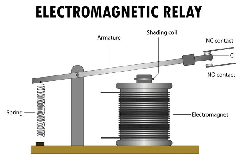
A typical electromechanical relay consists of several key components:
- Coil
- Magnetic core
- Armature
- Spring mechanism
- Normally open contacts
- Normally closed contacts
- Common terminal
When the rated control voltage is applied to the relay coil, the coil generates a magnetic field.
This magnetic force moves the armature and changes the state of the contacts.
As a result, the relay can control one electrical circuit using a signal from another circuit.
One of the most important characteristics of this arrangement is that:
the control circuit and switched circuit do not need to be electrically connected directly.
This electrical separation is one of the main reasons relays continue to be widely used in industrial automation.
3. How Does a Relay Work?
A simple PLC-controlled solenoid valve provides a good example.
Suppose a water treatment system needs to open a refill valve when the tank level falls below a preset value.
The control sequence might be:
Level sensor → PLC input → PLC logic → PLC output → intermediate relay → solenoid valve
When the PLC determines that refilling is required:
- The PLC output sends a control signal.
- The relay coil is energized.
- The coil generates a magnetic field.
- The armature moves.
- The normally open contact closes.
- Power is supplied to the solenoid valve.
- The valve operates.
When the PLC stops sending the output signal:
- The relay coil is de-energized.
- The magnetic field disappears.
- The spring returns the armature to its original position.
- The relay contacts return to their normal state.
- Power to the solenoid valve is disconnected.
Although this appears to be a simple switching action, the relay provides an important electrical interface between the PLC and the field device.
4. Why Do PLC Control Systems Use Relays?
A common question in industrial automation is:
If a PLC already has output terminals, why not connect every field device directly to the PLC?
The answer is that PLC outputs are not always suitable for directly driving every type of load.
This is one of the main reasons intermediate relays are commonly installed in PLC control cabinets.
4.1 Electrical Isolation
PLCs are critical control devices, while field equipment often operates in a more electrically demanding environment.
Typical loads include:
- Solenoid valves
- Contactor coils
- Alarm devices
- Fan control circuits
- Pump control circuits
When these loads switch on or off, they may generate electrical noise, inductive voltage spikes, or other transient disturbances.
Installing a relay between the PLC and the load can provide additional electrical separation between the control electronics and the field circuit.
This can help reduce the exposure of PLC outputs to disturbances generated by external equipment.
4.2 Expanding PLC Output Contacts
One PLC output normally represents one logical control point.
However, a single control command may sometimes need to trigger several independent actions.
For example, when a pump starts, the system may need to:
- Energize a contactor
- Turn on a running indicator
- Send a status signal to another system
- Start auxiliary equipment
A relay with multiple contact sets can use one PLC output to operate several electrically independent circuits.
This function is commonly referred to as contact multiplication or contact expansion.
4.3 Converting Between Different Voltage Levels
Industrial control cabinets often contain multiple voltage levels, such as:
- 24 V DC
- 48 V DC
- 110 V AC
- 220 or 230 V AC
For example, the PLC output may operate at 24 V DC, while an alarm circuit may require a higher AC voltage.
A relay allows a 24 V DC coil to switch a separate AC circuit without directly connecting the two voltage systems.
This makes relays especially useful for signal and voltage interface conversion.
4.4 Easier Maintenance and Troubleshooting
If a PLC is connected directly to many field devices, troubleshooting external circuit faults may become more complicated.
With plug-in intermediate relays, maintenance personnel can often inspect:
- Relay indication
- Coil energization
- Contact state
- Field-side voltage
to determine whether a fault is located on the PLC side, relay side, or load side.
For industrial systems designed for long-term operation, this can significantly improve maintenance convenience.
5. What Are the Main Types of Relays?
Relays are available in many designs and operating principles.
The following types are commonly found in industrial automation systems.
5.1 Electromechanical Relay
An electromechanical relay uses an energized coil to generate magnetic force and physically move mechanical contacts.
This is one of the most familiar relay types used in industrial control cabinets.
Typical advantages include:
- Simple operating principle
- Clear electrical isolation
- Multiple contact configurations
- Easy replacement
- Wide availability
- Relatively low cost
Common applications include:
- PLC output interfacing
- Solenoid valve control
- Contactor coil control
- Alarm circuits
- Indicator lamps
- Signal conversion
- Electrical interlocking
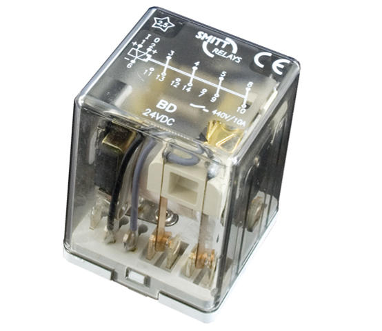
Many plug-in intermediate relays used in industrial panels are electromechanical relays.
5.2 Solid State Relay
A solid state relay, commonly abbreviated as SSR, performs switching using semiconductor components rather than mechanically moving contacts.
Because it has no conventional mechanical switching contacts, an SSR can be useful in applications requiring frequent switching.
Typical applications include:
- Electric heating systems
- Temperature control
- Industrial ovens
- High-frequency switching
- Repetitive cyclic loads
Solid state relays can offer advantages such as fast switching and no mechanical contact wear.
However, they are not automatically the best choice for every application.
Designers must also consider:
- Leakage current
- On-state voltage drop
- Heat generation
- Heat dissipation
- Load type
- Short-circuit protection
The choice between an SSR and an electromechanical relay should therefore be based on the actual operating conditions.
5.3 Intermediate Relay
The term intermediate relay generally describes the relay’s function within a control circuit rather than a completely different operating principle.
It is commonly installed between:
PLC output → field equipment
Typical functions include:
- Electrical isolation
- Signal interfacing
- Contact expansion
- Voltage conversion
- Load switching
DIN-rail-mounted plug-in relays are widely used as intermediate relays in industrial control panels.
5.4 Time Relay
A standard relay normally responds immediately when its coil is energized or de-energized.
A time relay, also known as a timer relay, introduces a predefined time delay.
Typical operating functions include:
On-delay:
The output changes state after the input signal has remained active for a preset time.
Off-delay:
The output remains active for a preset period after the control signal is removed.
Time relays are commonly used for:
- Sequential motor starting
- Delayed fan shutdown
- Star-delta motor starting
- Conveyor sequencing
- Alarm delays
- Equipment sequencing
Many timing functions are now performed within PLC programs, but timer relays are still useful in simple standalone circuits or systems without a PLC.
5.5 Thermal Overload Relay
A thermal overload relay is primarily used to protect electric motors against prolonged overload conditions.
When motor current remains above an acceptable level for a sufficient period, the thermal element responds and causes the protection mechanism to trip.
This typically interrupts the control circuit and stops the motor.
An important distinction is:
A thermal overload relay is designed mainly for overload protection and should not be treated as a replacement for short-circuit protection.
Motor control systems normally combine overload relays with appropriate circuit protection devices and contactors.
5.6 Safety Relay
Safety relays are designed for applications involving functional safety.
Typical applications include:
- Emergency stop circuits
- Safety doors
- Light curtains
- Two-hand controls
- Machine guarding systems
A safety relay does more than simply switch an output.
Depending on the design, it may use monitoring, redundancy, fault detection, or controlled reset functions to improve the reliability of safety circuits.
Where personnel safety is involved, an ordinary intermediate relay should not automatically be used as a substitute for a properly designed safety relay or safety controller.
6. Typical Relay Applications in Industrial Automation
Relays are used throughout industrial automation.
Here are several common examples.
Application 1: PLC Control of a Solenoid Valve
In water treatment, process automation, and machine control systems, PLCs frequently operate pneumatic or hydraulic valves through solenoid coils.
A common circuit structure is:
PLC → Intermediate relay → Solenoid valve
The relay provides an interface between the controller and the field load.
Application 2: PLC Control of a Contactor
For motors such as pumps, fans, and conveyors, the PLC normally does not switch the main motor power circuit directly.
A common arrangement is:
PLC → Intermediate relay → Contactor coil → Motor
In this arrangement:
- The PLC performs logic control.
- The intermediate relay provides signal interfacing.
- The contactor switches the motor power circuit.
Application 3: Liquid Level Control System
Consider an industrial water tank.
A level transmitter measures the liquid level and sends a signal to the PLC.
When the level falls to the refill setpoint:
PLC output → Relay energizes → Refill equipment starts
When the level reaches the stop setpoint:
PLC output turns off → Relay resets → Refilling stops
This type of control architecture is widely used in:
- Water storage tanks
- Process vessels
- Fire water tanks
- Sewage lift stations
- Industrial water treatment systems
Application 4: Alarm Systems
When an automation system detects an abnormal condition, the PLC may need to activate:
- Audible alarms
- Beacons
- Buzzers
- Warning lights
- Remote alarm contacts
A relay can convert the PLC’s electrical output into an isolated dry contact or another type of switching signal for external systems.
Application 5: Equipment Interlocking
Suppose a machine is allowed to start only after a cooling-water pump is running.
This is an example of interlocking control.
Relay contacts can be used to establish hardwired interlocks between different machines or circuits.
Although modern PLCs can implement complex software interlocks, hardwired contacts still have practical value in many industrial control applications.
7. What Do NO, NC, and COM Mean on a Relay?
When reading relay wiring diagrams, three abbreviations appear frequently:
- COM
- NO
- NC
Understanding these terminals is essential for correct relay wiring.
COM — Common
COM means Common.
It is the moving or shared contact terminal used with either the NO or NC connection.
NO — Normally Open
NO means Normally Open.
When the relay coil is not energized:
COM and NO are open.
When the relay coil is energized:
COM and NO become connected.
NC — Normally Closed
NC means Normally Closed.
When the relay coil is not energized:
COM and NC are connected.
When the coil is energized:
COM and NC open.
Automation engineers can therefore select normally open or normally closed logic according to the required control function.
8. Relay vs Contactor: What Is the Difference?
Relays and contactors operate according to similar switching concepts, so they are sometimes confused.
A practical distinction is:
Relays are generally used in control circuits and for relatively smaller loads, while contactors are typically designed for frequent switching of higher-power loads such as motors.
For example, when a PLC controls a three-phase pump, an ordinary intermediate relay would normally not be used to switch the three-phase motor power directly.
A more typical architecture is:
PLC → Intermediate relay → Contactor → Three-phase motor
Here:
- The PLC performs the control logic.
- The relay interfaces the control signal.
- The contactor switches the motor’s main power circuit.
For this reason, a relay should not be selected as a direct substitute for a contactor simply because its nominal current rating appears high enough.
9. How to Select the Right Relay for an Automation System
Relays are relatively simple components, but incorrect selection can lead to:
- Contact burning
- Contact welding
- Coil overheating
- Frequent relay failure
- PLC output problems
- Unexpected equipment operation
Several factors should therefore be evaluated.
9.1 Coil Voltage
First, determine the control voltage.
Common industrial relay coil voltages include:
- 12 V DC
- 24 V DC
- 48 V DC
- 110 V AC
- 220/230 V AC
If the PLC provides a 24 V DC output, the relay coil should be selected accordingly unless another interface circuit is used.
9.2 Contact Rating
Every relay has a specified contact load capacity.
However, the contact rating cannot be evaluated from current alone.
Engineers should also consider:
- AC or DC switching
- Load voltage
- Continuous current
- Inrush current
- Load characteristics
A relay marked with a particular current rating may have significantly different switching capability depending on the type of load.
9.3 Load Type
Different loads can place very different electrical stress on relay contacts, even when their steady-state current is similar.
Common loads include:
- Resistive loads
- Inductive loads
- Motors
- Lamps
- Solenoid valves
- Contactor coils
Inductive loads such as coils and solenoid valves can generate high transient voltages when switched off.
Appropriate surge suppression should therefore be considered according to the circuit design.
9.4 Number of Contacts
Relays are available with:
- One changeover contact
- Two changeover contacts
- Four changeover contacts
- Multiple independent contact sets
If one control signal needs to operate several independent circuits, the required number and configuration of contacts should be determined in advance.
9.5 Switching Frequency
If a relay switches only a few times per hour, an electromechanical relay may be perfectly suitable.
If a load must switch multiple times per second, mechanical contact life may become a limiting factor.
For high-frequency switching, a solid state relay may be more appropriate.
9.6 Installation and Maintenance
DIN-rail mounting is common in industrial control cabinets.
Plug-in relays with replaceable relay bases can make maintenance and replacement much easier.
This can be particularly valuable in production environments where downtime needs to be minimized.
10. Common Relay Problems in Automation Systems
Why Is the Relay Energized but the Equipment Does Not Operate?
Check the following:
- Has the relay actually changed state?
- Is the COM terminal wired correctly?
- Is the correct NO or NC contact being used?
- Is voltage available on the contact side?
- Is the load circuit open?
- Are the relay contacts damaged?
Why Does a Relay Fail Frequently?
Common causes include:
- Load exceeds contact capacity
- Excessive inductive surge
- Switching frequency is too high
- Incorrect coil voltage
- High ambient temperature
- Relay type does not match the load
Relay selection should therefore not be based only on price or nominal current.
Does Every PLC Output Need an Intermediate Relay?
No.
If the PLC output rating, load characteristics, electrical isolation, and system design permit direct connection, certain loads can be driven directly.
However, an intermediate relay is often useful when:
- Voltage conversion is required
- Additional contacts are needed
- A dry contact output is required
- More separation between PLC and field circuitry is desired
- The load environment is electrically noisy
- Easier field maintenance is important
Whether a PLC output needs an intermediate relay should therefore be determined on a circuit-by-circuit basis.
11. Electromechanical Relay vs Solid State Relay: Which Should You Choose?
Neither technology is universally better.
Electromechanical relays are often suitable when:
- Switching frequency is relatively low
- Physical contact isolation is preferred
- Multiple changeover contacts are required
- Easy replacement is important
- The application is a general industrial control circuit
Solid state relays are often suitable when:
- High-frequency switching is required
- Heating loads are being controlled
- Temperature regulation is involved
- High switching cycle life is important
- Fast switching is required
The final choice should consider load type, current, switching frequency, ambient temperature, heat dissipation, leakage current, and maintenance requirements.
12. Will Relays Become Obsolete in Modern Automation?
As PLCs, distributed I/O, industrial networks, and semiconductor switching technologies continue to develop, some functions once performed by traditional relays are increasingly handled electronically.
For example, control sequences that once required multiple timer relays can now be implemented with a few lines of PLC logic.
Likewise, relay-based logic panels have largely been replaced by programmable controllers in many complex machines.
However, this does not mean relays will disappear from industrial automation.
Automation systems still need to solve practical problems such as:
How should controller signals interface with field loads?
How can different voltage systems be separated?
How can independent dry contacts be provided?
How can electrical isolation be achieved?
How can control panels remain easy to troubleshoot and maintain?
As long as these requirements remain, relays—or electronic devices performing similar interface functions—will continue to play an important role in industrial control systems.
13. Conclusion
A relay may not be the most sophisticated component inside an automation control cabinet, but it often performs a critical interface function.
Sensors collect field information, PLCs perform logical decisions, and relays frequently help translate those control decisions into actual actions by field devices.
From PLC output isolation and voltage conversion to contact expansion, solenoid valve control, contactor control, alarms, and equipment interlocking, relays are involved in many areas of industrial automation.
Understanding the relay working principle, different types of relays, and relay applications in automation systems is therefore fundamental for anyone working with industrial electrical control and PLC automation.
In real-world projects, relay selection should not be based only on coil voltage and contact current.
Engineers should also evaluate:
- Load type
- Inrush current
- Switching frequency
- Inductive surge
- Contact configuration
- Ambient conditions
- Installation method
- Maintenance requirements
By selecting the correct relay for the actual application, an automation system can achieve more reliable switching, better electrical interfacing, easier troubleshooting, and improved long-term maintainability.

