
In industries such as oil and gas, chemicals, power generation, pharmaceuticals, water treatment, and food processing, knowing how much material is inside a storage tank, reactor, or silo is essential for both operational efficiency and plant safety.
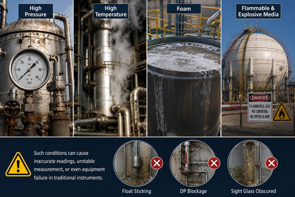
In the past, operators often relied on sight glasses, floats, differential pressure transmitters, or manual inspection to determine liquid levels. However, traditional measurement methods may require frequent maintenance or deliver unstable results when exposed to high temperatures, high pressures, steam, foam, or flammable and explosive media.
Guided wave radar level transmitters have become widely used because they provide continuous level measurement under many demanding process conditions. They measure level by transmitting electromagnetic pulses along a probe. Unlike mechanical float devices, they contain no continuously moving measuring parts and do not depend on process fluid density to calculate the level.
1. What Is Guided Wave Radar?
Guided wave radar, commonly abbreviated as GWR, is also known as a guided wave radar level transmitter, guided wave radar level sensor, or TDR level transmitter.
The term “guided wave” means that the electromagnetic signal does not radiate freely throughout the vessel. Instead, it travels downward along a metal rod, cable, or coaxial probe.
The probe acts as a defined transmission path for the radar pulse, concentrating the signal energy and guiding it toward the surface of the material being measured.
When the electromagnetic pulse reaches the surface of a liquid or bulk solid, the dielectric properties of the surrounding medium change. This change causes part of the pulse energy to be reflected back toward the transmitter.
The instrument measures the time required for the pulse to travel from the transmitter to the material surface and return. Based on this travel time, it calculates the distance between the sensor reference point and the product surface. The measured distance is then converted into an actual level value using the configured vessel height.
This measurement method is based on Time Domain Reflectometry, commonly known as TDR. Guided wave radar is therefore often described as a TDR-based continuous level measurement technology in which radar pulses travel along a probe.
2. How Does a Guided Wave Radar Level Transmitter Work?
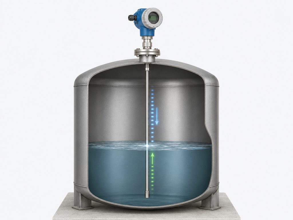
The guided wave radar measurement process can be divided into four basic stages: transmission, propagation, reflection, and calculation.
First, the electronic unit generates low-energy, extremely short, high-frequency electromagnetic pulses. These pulses travel downward along the rod, cable, or coaxial probe.
When the pulse reaches the surface of the process material, part of the electromagnetic energy is reflected. The reflected signal travels back upward along the same probe toward the transmitter.
The electronics record the round-trip travel time of the pulse. Advanced signal-processing algorithms then calculate the distance from the top reference point of the probe to the surface of the material.
Once the vessel reference height is known, the instrument can calculate the actual product level. The measurement can then be converted into a 4–20 mA signal, HART communication, fieldbus output, or another digital protocol for transmission to a distributed control system, programmable logic controller, or process monitoring platform.
A simple way to understand the principle is to imagine sending an echo along a rope. In a conventional non-contact radar instrument, the electromagnetic signal travels through the open vapor space. In a guided wave radar transmitter, the signal follows a metal probe, which provides a more focused and controlled transmission path.
Because the electromagnetic pulse is guided rather than freely radiated, guided wave radar may be less affected by narrow vessels, nearby internal structures, and beam divergence.
It is important to understand that guided wave radar does not determine level by sensing hydrostatic pressure. It also does not depend on buoyancy to move a mechanical component. The main function of the probe is to guide the electromagnetic signal.
3. Common Guided Wave Radar Probe Types
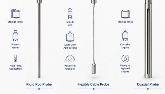
The three most common guided wave radar probe designs are rigid rod probes, flexible cable probes, and coaxial probes. Each design is suitable for different vessel structures, measuring ranges, and process media.
3.1 Rigid Rod Probe
A rigid rod probe normally consists of a straight metal rod. It offers a simple structure and good mechanical stability, making it suitable for liquid level measurement over short and medium measuring ranges.
Because the rod is rigid, it does not move as easily as a flexible cable. This makes it useful in tanks where there is moderate agitation, turbulence, or liquid surface movement.
However, long rigid probes can be difficult to transport and install. For tall vessels or sites with limited installation space, a flexible cable probe may be more practical.
3.2 Flexible Cable Probe
A cable probe uses a flexible metal cable and is commonly used in tall tanks, deep vessels, and some bulk-solid silos.
The cable can be manufactured according to the required measurement length. It is generally easier to transport and install than an extremely long rigid rod.
When cable probes are used for powders, granules, or other bulk solids, the mechanical load on the cable must be considered carefully. Falling material, product buildup, filling, and emptying can place significant tensile and lateral forces on the probe.
If the material tends to form large clumps, create strong side loads, or become wrapped around the cable, the mechanical strength of the probe and its anchoring arrangement must be evaluated.
3.3 Coaxial Probe
A coaxial probe usually consists of a central conductor surrounded by an outer metal tube. The electromagnetic signal travels mainly inside the coaxial structure.
This design concentrates the signal and reduces its sensitivity to nearby vessel walls and internal metal components. Coaxial probes are often suitable for narrow spaces, bypass chambers, and some low-dielectric-constant liquids.
However, the space inside a coaxial probe is relatively small. If the process material crystallizes, solidifies, plugs, or creates heavy coating, cleaning and maintenance may become more difficult.
The correct probe should be selected according to the dielectric properties, viscosity, corrosiveness, buildup tendency, vessel geometry, and available installation space.
4. Why Can Guided Wave Radar Operate in Difficult Process Conditions?
One of the most important characteristics of guided wave radar is that the radar pulse is concentrated around the probe.
Unlike ultrasonic measurement, electromagnetic waves do not require air or another gas as a transmission medium. As a result, guided wave radar can generally continue operating in vacuum conditions.
Compared with differential pressure measurement, guided wave radar directly measures the distance to the material surface. It does not calculate level from liquid-column pressure and product density.
When process fluid density changes, a differential pressure level measurement may require compensation. A guided wave radar measurement is generally not directly affected by the density change because it is based on pulse travel time rather than hydrostatic pressure.
The concentrated signal path may also make guided wave radar suitable for vessels containing steam, foam, turbulence, or narrow bypass chambers.
Guided wave radar can be used for liquids, slurries, some bulk solids, and liquid-liquid interface measurement. In addition, it contains no continuously moving mechanical measuring components.
However, “less affected” does not mean “completely unaffected.”
Severe product buildup, contact between the probe and metal structures, thick emulsion layers, incorrect dielectric settings, and poor installation locations can still cause false echoes, weak signals, or unstable measurements.
5. Can Guided Wave Radar Measure Oil-Water Interfaces?
In addition to measuring total liquid level, certain guided wave radar instruments can simultaneously measure the interface between two immiscible liquids, such as oil and water in a separator.
When the radar pulse reaches the surface of the upper liquid, part of the energy is reflected back to the transmitter. The remaining energy continues downward through the upper liquid.
When the pulse reaches the boundary between the upper and lower liquids, another change in dielectric properties occurs. This produces a second reflection.
By identifying both reflected signals, the instrument can calculate the total liquid level as well as the position of the interface.
Interface measurement is not possible for every combination of liquids. In general, the upper liquid should have a lower dielectric constant than the lower liquid, and there must be a sufficient dielectric difference between the two products.
The dielectric constant of the upper liquid should also remain reasonably stable. If it changes significantly, the pulse propagation speed and signal attenuation within the upper product may also change.
Oil-over-water applications are common because oil and water usually have very different dielectric properties. However, a thick or unstable emulsion layer between the two products can weaken or broaden the interface reflection, making the boundary more difficult to identify.
In these cases, the process conditions and the capabilities of the selected guided wave radar transmitter should be carefully evaluated.
6. Guided Wave Radar vs. Non-Contact Radar
A conventional radar level transmitter normally provides non-contact measurement. Its antenna transmits an electromagnetic signal through the vapor space inside the vessel. The signal reflects from the material surface and returns to the antenna.
The measuring components normally do not need to extend into or touch the process material.
Guided wave radar, by contrast, is a contact measurement technology. Its metal probe extends into the vessel and is normally in continuous contact with the process medium.
Neither technology is universally better than the other.
Because its signal travels along a probe, guided wave radar can be suitable for narrow vessels, bypass chambers, interface applications, and some products with weak radar reflectivity.
Non-contact radar does not use a long immersed probe. It may therefore be a better choice for strongly corrosive products, severe buildup, hygienic processes, or applications where contact between the measuring device and the product is undesirable.
A proper comparison should consider more than instrument price or stated accuracy. Vessel height, process medium, temperature, pressure, internal obstructions, nozzle size, installation access, and maintenance requirements must all be evaluated.
7. Common Applications of Guided Wave Radar
Guided wave radar level transmitters are used in many industries because they can support both continuous level measurement and interface measurement.
Oil and Gas
In the oil and gas industry, guided wave radar can be used in crude oil tanks, oil-water separators, buffer vessels, process tanks, and fuel storage systems.
It can measure total liquid level or, with a suitable instrument and process conditions, the interface between oil and water.
Chemical Processing
In chemical plants, guided wave radar is commonly installed in reactors, solvent tanks, acid and alkali storage vessels, and process tanks containing steam or foam.
For corrosive chemicals, the compatibility of the probe, process seal, flange, and wetted materials must be checked carefully.
Power Generation
Power plants may use guided wave radar to measure condensate, fuel oil, demineralized water, and liquids in high-temperature process vessels.
For high-temperature, high-pressure, or saturated-steam applications, a transmitter with suitable process ratings, sealing technology, and compensation features is required.
Water and Wastewater Treatment
In water treatment facilities, guided wave radar may be used in chemical dosing tanks, wastewater vessels, sludge containers, and narrow measurement chambers.
The instrument should be selected according to the possibility of coating, solids accumulation, foam, and corrosion.
Food and Pharmaceutical Production
Guided wave radar may also be used in food, beverage, and pharmaceutical applications.
However, hygienic process connections, surface finish, cleanability, sterilization procedures, and the risk of product residue should be considered. In some hygienic applications, non-contact radar may be preferable because there is no long probe immersed in the product.
Bulk Solids
Certain guided wave radar instruments can measure powders, granules, and other bulk materials.
For these applications, the selection process should include dielectric properties, dust generation, filling impact, material buildup, tensile load, and the shape of the material surface.
8. Key Factors When Selecting a Guided Wave Radar Transmitter
Selecting the correct guided wave radar requires a detailed understanding of the application.
The first step is to determine whether the product is a liquid, slurry, powder, or granular solid. It is also necessary to decide whether the instrument will measure total level only or both total level and interface.
Dielectric Constant
The dielectric constant of the material is one of the most important selection parameters.
In general, a product with a higher dielectric constant creates a stronger radar reflection. A low-dielectric material produces a weaker reflection and may require a more sensitive instrument or a more appropriate probe design.
Temperature and Pressure
The transmitter, process connection, seal, and probe must be rated for the maximum and minimum process temperatures and pressures.
Selection should not be based only on normal operating conditions. Startup, shutdown, cleaning, sterilization, and abnormal process conditions should also be considered.
Corrosion and Chemical Compatibility
All wetted components must be compatible with the process medium.
The probe, flange, seals, gaskets, and process connections may be exposed to the product for long periods. Incorrect material selection can result in corrosion, leakage, contamination, or premature failure.
Viscosity, Crystallization, and Coating
Highly viscous liquids, crystallizing chemicals, sticky products, and coating media can accumulate on the probe.
A thin, uniform coating may have limited impact in some applications, while heavy or uneven buildup can create false reflections and weaken the actual level signal.
Vessel Height and Geometry
The vessel height determines the required probe length and measurement range.
The locations of agitators, heating coils, ladders, support structures, internal piping, and vessel walls should be reviewed before selecting the installation point.
The probe should not touch the vessel wall or internal metal components, because direct contact can interfere with the measuring signal.
Filling and Discharge Conditions
A guided wave radar probe should not normally be positioned directly in the main filling stream.
Strong incoming flow can strike the probe, create excessive turbulence, cause cable movement, or produce coating. In bulk-solid applications, falling material may also create high mechanical loads.
Output and Communication
The required output should match the control and automation system.
Common options include 4–20 mA, HART, fieldbus protocols, and other digital communication methods. Advanced instruments may also provide remote diagnostics, echo-curve analysis, event history, and condition-monitoring features.
Safety and Certification
Applications involving flammable, explosive, toxic, high-pressure, or high-temperature media may require hazardous-area approval or functional safety certification.
The required explosion protection, Safety Integrity Level, environmental rating, and industry-specific approvals should be defined before purchase.
9. Common Guided Wave Radar Installation Problems
If a guided wave radar produces unstable or jumping level readings after installation, the transmitter itself is not necessarily defective.
Many measurement problems are caused by installation conditions or incorrect configuration.
For example, a probe installed too close to the vessel wall may detect unwanted reflections. A probe touching an internal metal structure can create signal interference.
A probe positioned directly below an inlet may be exposed to strong product flow and mechanical impact. A cable probe installed in a highly agitated tank may move excessively if it is not properly selected or secured.
Heavy crystallization, buildup, or coating on the probe can also reduce the strength of the true level reflection.
During commissioning, the vessel height, probe length, upper and lower blocking distances, material parameters, and output range should be entered correctly.
The echo curve should be reviewed to determine whether the transmitter is identifying the actual material surface, the probe end, or a fixed obstruction inside the vessel.
Guided wave radar is a precision industrial measuring technology. For applications involving high pressure, high temperature, flammable products, explosive atmospheres, or toxic chemicals, installation and maintenance should be carried out by trained and authorized personnel in accordance with the manufacturer’s instructions and applicable safety regulations.
10. Frequently Asked Questions About Guided Wave Radar
Does a Guided Wave Radar Require Regular Calibration?
Guided wave radar calculates distance mainly from the travel time of an electromagnetic pulse. It does not normally depend on product density in the same way as differential pressure level measurement.
However, the measurement range, reference height, probe length, and echo curve should still be checked during commissioning. Verification may also be necessary after a probe replacement, process change, or major maintenance activity.
Can Guided Wave Radar Measure Solid Materials?
Certain rod and cable guided wave radar instruments can measure powders, pellets, and granular solids.
The application must account for dielectric constant, material buildup, dust, filling impact, tensile force, and the shape of the material surface.
Not every liquid-level guided wave radar transmitter is suitable for bulk-solid measurement.
Does Foam Affect Guided Wave Radar?
Light foam does not always block a guided radar signal completely, because the electromagnetic pulse follows the probe.
However, the effect depends on the thickness, density, moisture content, conductivity, and stability of the foam.
Thick, wet, conductive, or highly variable foam may create additional reflections or weaken the reflection from the actual liquid surface.
Can Guided Wave Radar Measure Corrosive Liquids?
Guided wave radar can be used for some corrosive liquids when the probe, process seal, flange, and other wetted materials are chemically compatible with the product.
For strongly corrosive media, a non-contact radar transmitter may sometimes reduce the number of immersed components and lower the risk of corrosion.
The final selection should be based on chemical compatibility, process conditions, and maintenance requirements.
Is Guided Wave Radar Affected by Product Density?
Guided wave radar does not calculate level from hydrostatic pressure, so normal changes in product density generally do not directly change the measured level.
However, changes in composition may alter the dielectric constant of the material. If the dielectric properties change significantly, signal strength and interface measurement performance may be affected.
Can Guided Wave Radar Work in a Vacuum?
Because guided wave radar uses electromagnetic energy rather than sound waves, it does not require air as a propagation medium.
It can therefore generally operate in vacuum vessels, provided the selected transmitter, probe, process connection, and seals are suitable for the operating conditions.
What Causes False Echoes in Guided Wave Radar?
Common causes include nearby metal structures, direct probe contact with the vessel wall, heavy buildup, incorrect probe length settings, strong inlet flow, unsuitable installation locations, and unexpected dielectric layers.
Reviewing the echo curve is one of the most effective ways to identify the source of a false reflection.
Conclusion
Guided wave radar is more than a conventional radar transmitter fitted with a metal rod or cable.
It is a continuous level measurement technology based on Time Domain Reflectometry. Electromagnetic pulses travel along a probe, reflect from the surface of the process material, and return to the transmitter.
Guided wave radar offers several important advantages. It provides a focused signal path, contains no continuously moving measuring parts, can support both level and interface measurement, and is generally not directly affected by changes in product density.
These characteristics make it valuable in industries such as oil and gas, chemicals, power generation, water treatment, food processing, and pharmaceuticals.
However, guided wave radar is not a universal solution for every application.
Probe material, dielectric constant, product buildup, vessel geometry, temperature, pressure, internal structures, and installation location can all affect performance.
The best measurement results are achieved by carefully evaluating the process conditions, selecting the correct probe design and process connection, and following proper installation and commissioning procedures.

