
If you have worked with radar level meters, you may already be familiar with terms such as measurement range, dead zone, dielectric constant, and 80 GHz radar.
However, there is another important term in the level measurement industry that many ordinary users rarely hear about:
false echo.
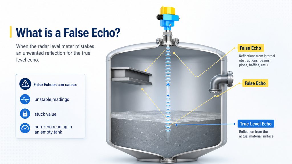
Many field problems—such as unstable readings, a level value that does not change, a non-zero reading in an empty tank, or a measurement value that suddenly becomes “stuck” at a certain height—do not necessarily mean that the sensor is damaged or that the radar level meter lacks sufficient accuracy.
The real problem may be much simpler:
The instrument has mistaken a reflection that does not come from the actual material surface for the true level echo.
That unwanted reflection is known as a false echo.
1. First, What Does a Radar Level Meter Actually “See”?
To understand false echoes, it is important to first understand that a radar level meter does not literally “see” the liquid surface like a camera.
A radar level meter transmits electromagnetic waves into a vessel. When these waves reach the surface of the measured medium, part of the energy is reflected back toward the sensor.
The instrument receives the returning signal and uses the signal information to calculate the distance between the sensor and the material surface. It then converts this distance into a liquid level or solids level value.
Under ideal conditions, the process is very simple:
Radar transmission → reflection from the material surface → radar reception → level calculation
The problem is that real industrial tanks are rarely this simple.
Inside a vessel, there may be:
- agitator blades
- heating coils
- structural supports
- ladders
- inlet pipes
- spray devices
- reinforcing structures
- weld seams
- mounting nozzles
- other internal mechanical components
Radar waves can also reflect from these objects.
As a result, the radar level meter may receive not just one echo, but many echoes at the same time.
The signal reflected from the actual product surface is normally considered the valid echo or true level echo.
Reflections generated by tank structures, internal obstacles, or other non-target surfaces may become false echoes.
2. What Exactly Is a False Echo?
In simple terms:
A false echo is a reflected signal that does not come from the actual material level but may still be interpreted by the level meter as a valid level signal.
Here is a simple example.
Suppose a tank is 10 meters high, and the actual liquid surface is 6 meters away from the radar sensor.
Under normal conditions, the radar should identify the echo at 6 meters as the liquid surface.
However, imagine that there is a metal support beam located 2 meters below the sensor. Because metal is highly reflective, the beam may generate a very strong radar echo.
The instrument may then detect:
- 2 meters: strong reflection from the metal beam
- 6 meters: reflection from the actual liquid surface
A person who understands the tank structure knows that the 2-meter signal comes from the beam and that the 6-meter signal is the real liquid level.
But the radar instrument does not automatically know this.
It must determine which echo represents the actual level by analyzing factors such as:
- echo position
- signal strength
- historical measurement behavior
- echo tracking
- signal processing algorithms
- false echo suppression
This is one reason why signal processing is such an important part of modern radar level measurement.
3. What Causes False Echoes?
3.1 Reflections from Internal Tank Obstructions
This is one of the most common causes of false echoes.
If agitators, support beams, pipes, ladders, heating coils, or other structures are located within the radar beam, they can reflect the transmitted radar signal.
Metal objects are especially strong reflectors.
If an obstruction is close to the antenna, the reflected signal may even be stronger than the echo coming from the actual product surface.
This is why installing a radar level meter is not simply a matter of asking:
“Can the instrument physically be mounted here?”
A more important question is:
“What is located inside the radar beam?”
3.2 Reflections from Mounting Nozzles
Radar level meters are often installed on mounting nozzles or standpipes.
If the nozzle is too long, too narrow, or improperly matched to the antenna design, part of the radar energy may reflect inside the nozzle.
This can generate unwanted echoes before the radar signal even reaches the material surface.
For this reason, nozzle diameter, nozzle length, antenna position, and mounting geometry should not be treated as minor installation details.
They can directly affect measurement performance.
3.3 Radar Beam Hitting the Tank Wall
If the sensor is installed in an unsuitable position, or if the radar axis is not correctly directed toward the material surface, part of the radar energy may hit the tank wall.
The tank wall itself, weld seams, reinforcing rings, and other structural features can create stable reflections.
This issue can become especially important in:
- narrow vessels
- small tanks
- tall and slim containers
- vessels with complex internal structures
3.4 Periodic Interference from Agitators
Reactors and mixing tanks are classic applications where false echoes can occur.
As an agitator rotates, its blades repeatedly move into and out of the radar beam.
When a blade enters the beam, it may generate a strong reflection. When it moves away, the reflection becomes weaker or disappears.
This means the echo profile may change periodically.
If the radar level meter does not have sufficiently robust echo recognition and tracking capabilities, the measured level may fluctuate in synchronization with the agitator.
3.5 Multiple Reflections and Multiple Echoes
Radar signals do not always travel directly to the liquid surface and return only once.
In some vessels, the signal may reflect multiple times between:
- the material surface
- the tank roof
- the tank wall
- internal structures
These repeated reflections can generate additional echo peaks.
Therefore, seeing several peaks on an echo curve does not necessarily mean that there are several material surfaces inside the tank.
Some of them may simply be the result of multiple reflections.
3.6 A Weak True Echo Can Make False Echoes More Significant
Another common situation is easy to misunderstand.
Sometimes the false echo has not become stronger.
Instead, the true level echo has become weaker.
This may happen because of:
- low-reflectivity media
- heavy foam on the liquid surface
- turbulent liquid surfaces
- sloped bulk solids surfaces
- severe dust
- condensation on the antenna
- material buildup on the antenna
When the true echo becomes weak, a previously insignificant interference echo may suddenly become the strongest or most attractive signal for the instrument.
The radar level meter may then select the wrong echo.
This can result in incorrect level measurement.
4. What Problems Can False Echoes Cause?
A false echo does not always cause a complete measurement failure.
More often, it creates strange or inconsistent behavior that appears difficult to explain.
For example:
The actual level is changing, but the displayed value remains almost constant.
One possible reason is that the instrument has locked onto a fixed echo generated by an internal structure.
Another common symptom is:
The measurement works normally over most of the range, but suddenly jumps when the level reaches a certain height.
This may happen when the true level echo and an interference echo begin competing with each other in a particular measurement zone.
Other common symptoms include:
- a non-zero reading when the tank is empty
- abnormal readings near full tank conditions
- sudden upward or downward measurement jumps
- unstable values when an agitator starts operating
- accurate measurement in one part of the range but poor measurement in another
- intermittent loss-of-echo alarms
- measurement values becoming fixed at a specific distance
For this reason, when troubleshooting a radar level meter, checking only the power supply, 4–20 mA output, and measurement range settings may not be enough.
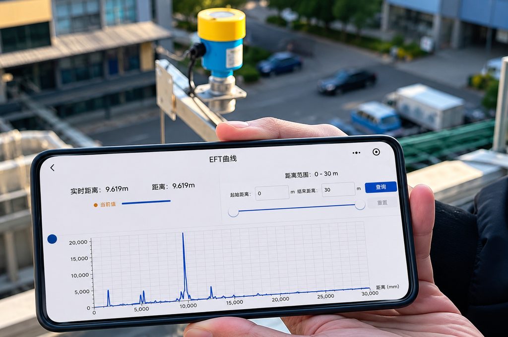
For echo-based level instruments, examining the echo curve can often provide much more useful diagnostic information.
5. What Is False Echo Suppression?
Since support beams, pipes, agitators, and other tank structures cannot always be removed, the radar level meter needs a way to distinguish between:
echoes that matter and echoes that should be ignored.
This is the purpose of false echo suppression.
Depending on the manufacturer, this function may be called:
- False Echo Suppression
- False Echo Mapping
- Interference Echo Suppression
- Interference Echo Mapping
- False Echo Learning
- Empty Tank Mapping
The terminology may differ, but the basic principle is similar.
During commissioning, the instrument can record known fixed interference echoes within a defined measurement range.
In subsequent operation, these stored echoes can be given lower priority so that the radar level meter is less likely to mistake them for the real product surface.
For example, imagine performing false echo mapping while the tank is empty.
The radar detects several reflections:
- a support beam at 2 meters
- a pipe at 4 meters
- the tank bottom at 8 meters
Because there is no product in the vessel, these reflections can be identified as fixed structural echoes.
After the instrument learns their positions and characteristics, it can more easily distinguish them from the moving level echo when the vessel begins to fill.
However, one point is very important:
False echo suppression does not simply mean deleting every unwanted-looking echo.
If the mapping range is configured incorrectly, the actual product surface may accidentally be stored as a false echo.
That can create new measurement problems.
For this reason, false echo mapping should normally be performed according to the instrument manufacturer’s commissioning instructions, ideally when the vessel is empty or when the actual level is accurately known.
6. Software Configuration Should Not Be the First Solution
When false echo problems occur in the field, one common reaction is:
“Can we just adjust the parameters and filter it out?”
Sometimes the answer is yes.
But a better approach is usually:
Solve the physical installation problem first, then optimize signal processing.
If a large metal pipe is positioned directly in the center of the radar beam, asking the software to ignore it creates an unnecessarily difficult measurement environment.
Several practical approaches can help.
Optimize the Installation Position
Position the radar level meter so that the main radar beam avoids:
- support beams
- internal pipes
- ladders
- agitators
- other major obstructions
Adjust the Sensor Direction
The radar should ideally be directed toward the material surface while minimizing reflections from tank walls and internal structures.
Choose an Appropriate Beam Angle
High-frequency radar level meters can generally achieve narrower beam angles.
One of the important advantages of many 80 GHz radar level meters is their highly focused beam.
A narrow beam can make it easier to avoid obstacles in:
- narrow tanks
- tall vessels
- reactors
- tanks with complex internal structures
However, an important point should be emphasized:
A narrow beam can reduce false echoes, but it does not mean false echoes can never occur.
Installation position, process conditions, antenna design, and signal processing remain important.
Analyze the Echo Curve
The echo curve can almost be considered the “ECG” of a radar level meter.
An experienced instrumentation engineer can use the echo curve to determine:
- where the true level echo is located
- where fixed interference echoes occur
- whether the echo strength is sufficient
- whether the instrument has selected the wrong echo
- whether the echo remains stable as the level changes
Compared with simply looking at the level value on the display, the echo curve provides much more diagnostic information.
Perform False Echo Mapping Correctly
If the vessel contains fixed obstacles that cannot be avoided, false echo mapping can be performed according to the manufacturer’s commissioning procedure.
This can be particularly useful for:
- reactors
- mixing tanks
- vessels with internal piping
- tanks with structural supports
- complex process vessels
7. Does a False Echo Mean the Radar Level Meter Is Poor Quality?
No.
Any measurement technology based on transmitting a signal and analyzing its reflection must deal with signal identification.
Radar level meters face this challenge, and so do ultrasonic level meters.
Guided wave radar operates differently because the signal travels along a probe or cable, but it can still experience interference and unwanted reflections under certain conditions.
The real measure of a level instrument’s capability is therefore not whether false echoes exist.
The more important question is:
Can the instrument reliably identify the true product level in a complex echo environment?
This is why modern radar level meters should be evaluated on more than just:
- measurement accuracy
- measuring range
- operating frequency
Other important factors include:
- antenna design
- dynamic range
- echo tracking capability
- signal processing algorithms
- interference suppression
- false echo mapping
- commissioning and diagnostic functions
8. An Often-Ignored Fact: Product Selection Is Only the Beginning
A great deal of attention in level measurement projects is often focused on product specifications:
Should you choose 80 GHz radar or another frequency?
Should the instrument be two-wire or four-wire?
Should the accuracy be ±1 mm or ±2 mm?
Should the measuring range be 30 meters or 50 meters?
All of these questions are important.
But once the instrument reaches the field, even a radar level meter with excellent specifications can perform poorly if it is installed directly above:
- an inlet stream
- an agitator shaft
- a large metal structure
- a poorly designed nozzle
On the other hand, a well-chosen installation position can significantly reduce commissioning and troubleshooting difficulties.
For complex tanks, instead of waiting until installation is complete and then trying to eliminate false echoes, it is better to consider several questions during the design stage:
Where will the radar beam travel?
What objects will be located inside the beam?
From the highest level to the lowest level, will the true product echo remain easy to identify?
In many applications, answering these questions is more valuable than simply comparing specification sheets.
9. Conclusion: Understanding False Echoes Means Understanding Radar Level Measurement
“False echo” may sound like a small technical term, but it represents one of the most important challenges in radar level measurement:
How does the instrument identify the true material level among many reflected signals in a complex vessel?
Support beams, pipes, agitators, mounting nozzles, tank walls, and multiple reflections can all generate interference echoes.
At the same time, foam, turbulence, low-reflectivity media, sloped solids surfaces, condensation, and product buildup can weaken the true echo and make false echoes more significant.
The solution is therefore not simply to press a “false echo suppression” button.
A more reliable approach combines:
correct instrument selection + proper installation + echo curve analysis + false echo suppression + process optimization
The next time a radar level meter suddenly produces an unstable reading—or the actual level changes while the displayed value remains fixed—do not immediately assume that the instrument has failed.
Take a look at the echo curve first.
The signal that appears to represent the level may not actually come from the material surface at all.
It may be one of the most important yet least understood phenomena in level measurement:
a false echo.
Frequently Asked Questions
1. What is a false echo in a radar level meter?
A false echo is a reflected signal that does not originate from the actual material surface but is still received by the radar level meter. Common sources include support beams, pipes, agitators, tank walls, and mounting nozzles.
2. Can false echoes cause unstable or jumping level readings?
Yes. If a false echo has a similar strength to the true level echo, or if the true echo suddenly becomes weaker, the instrument may select the wrong signal. This can cause measurement jumps, fixed readings, loss-of-echo conditions, or alarms.
3. Can an 80 GHz radar level meter still experience false echoes?
Yes. An 80 GHz radar level meter typically has a narrower beam, which helps reduce interference from internal structures. However, it cannot completely eliminate all false echoes. Correct installation and signal processing are still important.
4. When should false echo mapping be performed?
False echo mapping is generally performed when the vessel is empty, at a low level, or when the true level is accurately known. The exact procedure should follow the manufacturer’s commissioning instructions. Incorrect mapping can accidentally suppress the true level echo.
5. Should I replace the radar level meter if false echoes occur?
Usually not immediately. First check the installation position, radar beam path, internal obstructions, antenna condition, and echo curve. Then determine whether parameter adjustment, false echo mapping, installation changes, or a different type of level meter is necessary.

