
During the installation and commissioning of a radar level meter, parameters such as measuring range, high level, low level, distance offset, and dead zone can directly affect measurement performance. Among them, the minimum distance is an important parameter that is often overlooked, even though it has a significant impact on measurement stability at high liquid levels.
Some users assume that the smaller the minimum distance is set, the larger the usable measuring range will become. In practice, however, this is not necessarily true. Radar level meters have certain near-range measurement limitations. If the liquid surface gets too close to the antenna or measurement reference point, the instrument may experience difficulties in identifying the correct echo, increased false echoes, unstable readings, or even temporary loss of the level signal.
Therefore, understanding what the minimum distance actually means is more important than simply remembering a specific numerical value.
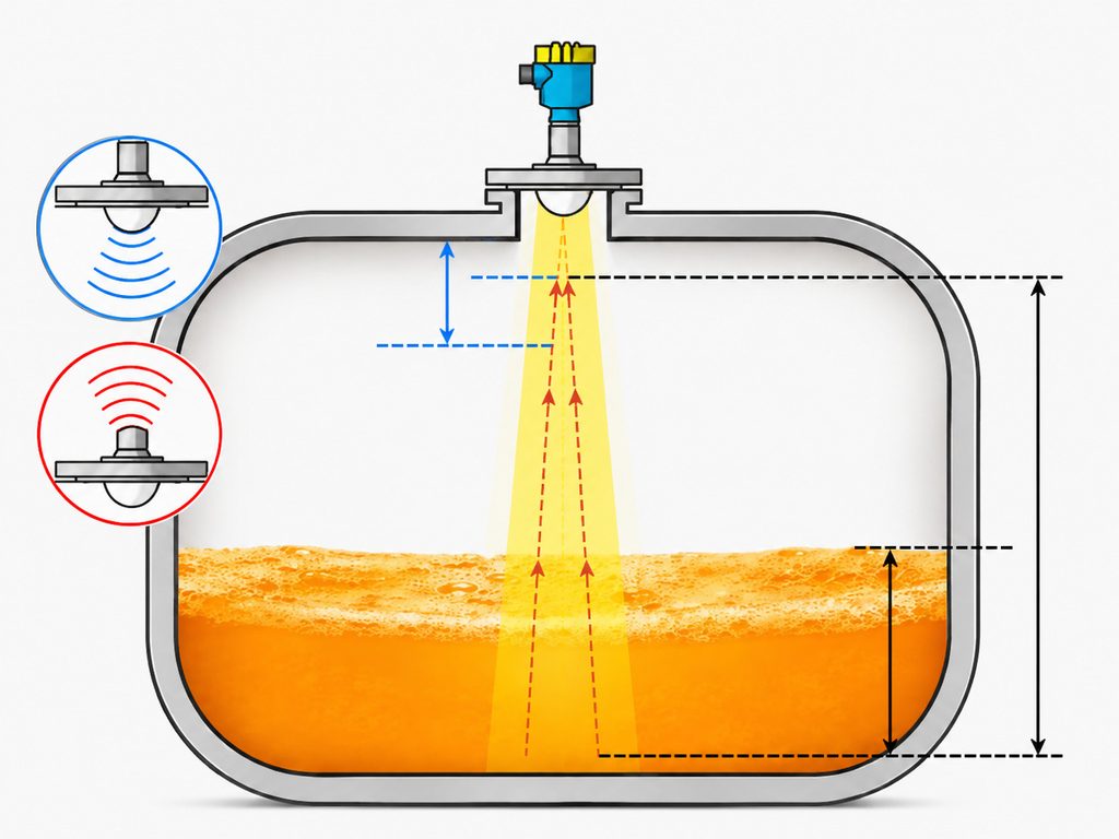
1. What Is the Minimum Distance of a Radar Level Meter?
A radar level meter works by transmitting high-frequency electromagnetic waves toward the surface of the measured medium. When the radar signal reaches the liquid surface, part of the energy is reflected back to the antenna. The instrument then calculates the distance between the radar sensor and the liquid surface based on the signal travel time or frequency change, and converts that distance into a level value.
The minimum distance can generally be understood as the minimum spacing that should be maintained between the radar measurement reference point and the surface of the measured medium to ensure reliable measurement.
For example, under the specified measuring conditions of certain 80 GHz radar level meters, the minimum distance between the target surface and the antenna lens is 0.15 m. Liquid measurement accuracy is evaluated when the measurement distance is greater than 0.15 m and remains within the effective measuring range.
However, one point must be emphasized:
A minimum distance of 0.15 m is not a universal value for all radar level meters.
Different radar frequencies, antenna structures, process connections, mounting nozzles, signal-processing algorithms, and product models can have different near-range measurement capabilities.
For actual applications, users should always refer to the technical specifications and measurement conditions of the specific radar level meter being used rather than applying the minimum distance from another model.
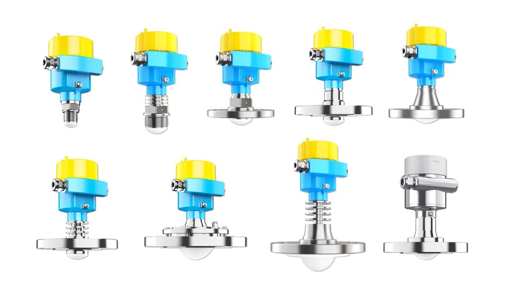
2. Why Can’t a Radar Level Meter Measure Infinitely Close to the Liquid Surface?
In theory, radar waves travel extremely fast, so it may seem that measuring a closer target should be easier. In industrial applications, however, the situation is considerably more complicated.
When the liquid surface is very close to the antenna, several signals may be concentrated within the same short-distance region, including:
- Internal antenna reflections
- Reflections from the process connection
- Reflections from the vessel roof
- Nozzle-related echoes
- Mechanical structures near the antenna
The true liquid-level echo can then appear very close to these fixed reflections, making it more difficult for the radar electronics to identify and track the correct signal.
This problem may become more noticeable in vessels with agitation, foam, vapor, condensation, or rapidly fluctuating liquid surfaces.
For example, when the liquid rises quickly into the near-range measurement area, the position and amplitude of the echo peak may change rapidly. If insufficient measurement margin has been reserved during parameter configuration, the level reading may fluctuate temporarily or become unstable.
Therefore, the purpose of radar level meter parameter setting is not to reduce the minimum distance to the lowest possible value. Instead, the goal is to ensure that the normal operating liquid level always remains within a stable and reliable measurement zone.
3. What Is the Difference Between Minimum Distance, Dead Zone, High Level, and Measuring Range?
These terms are frequently confused during radar level meter configuration.
First, the minimum distance primarily describes the near-range measuring capability or reliable measuring boundary of the instrument.
A dead zone, on the other hand, may refer to a signal-processing setting on certain radar level meters. It can be used to ignore echoes within a specified near-range area so that unwanted reflections do not participate in the level calculation.
The two concepts are related, but they should not automatically be considered identical.
The high level normally represents the liquid position corresponding to a full vessel or 100% level.
The low level usually represents the empty vessel position or the point defined as 0% level.
For radar level meters with a 4–20 mA output, high and low level settings often determine the calibration range of the analog output as well.
The measuring range generally defines the distance region in which the radar instrument searches for and processes valid echoes.
For many radar level instruments, the measuring range limits the algorithmic search area, while the high-level setting corresponds to the full position and the low-level setting corresponds to the empty position. These values are also related to the 4–20 mA output range.
Therefore, commissioning should not stop after entering a minimum distance value.
The measurement reference point, near-range limitation, high level, low level, and measuring range should be configured as one complete measurement system.
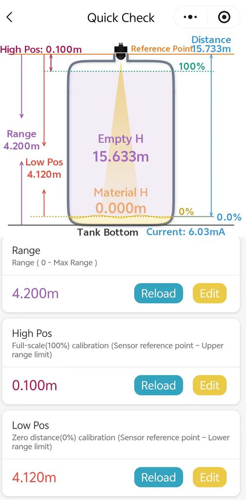
4. How Should the Minimum Distance of a Radar Level Meter Be Set?
The first step is to determine the measurement reference plane or sensor reference point.
This is the foundation of the entire parameter configuration.
The distance displayed by a radar level meter does not necessarily start from an arbitrary point on the top of the vessel. Depending on the sensor design, the measurement reference may be defined at the process connection, sensor reference plane, antenna reference point, or another specified location.
For this reason, field technicians should not simply use the vessel roof as the zero point without checking the instrument documentation.
Once the reference point has been confirmed, measure the actual distances from that point to:
- The vessel bottom
- The highest operating liquid level
- The lowest operating liquid level
Parameters such as measuring range, high level, and low level should all be calculated from the same reference system.
The second step is to confirm the minimum effective near-range measurement distance specified for the particular radar model.
For example, if a radar level meter specifies a minimum reliable measurement distance of 0.15 m from the antenna lens, the normal maximum liquid level should generally remain outside this near-range limitation.
In actual applications, additional margin should also be considered for:
- Liquid surface fluctuations
- Filling impact
- Foam
- Agitation
- Process safety requirements
The maximum operating level should not be designed to stop exactly at the theoretical measurement limit.
The third step is to configure the high level, low level, and measuring range.
For example, suppose:
- The distance from the radar reference point to the vessel bottom is 3.0 m.
- The maximum operating liquid level is 0.35 m below the radar reference point.
- The minimum operating level corresponds to a distance of 2.8 m.
If the near-range capability of the radar level meter reliably covers a distance of 0.35 m, the high-level calibration point can be configured accordingly, while the low-level point can be set according to the required operating range.
However, if the actual maximum liquid level is only 0.10 m from the radar reference point while the instrument requires a minimum reliable distance of 0.15 m, changing software parameters alone will not solve the problem.
In this situation, the installation height, process connection, nozzle arrangement, or radar model should be reconsidered.
5. What Happens If the Minimum Distance Is Set Too Small?
One of the most common problems is unstable measurement at high liquid levels.
When the medium enters a non-ideal near-range measurement region, the liquid-level echo may be affected by fixed reflections around the antenna.
Typical symptoms include:
- Sudden level jumps
- A distance reading that becomes fixed
- An output value that reaches 100% and no longer changes
- Intermittent loss of the valid echo
- Unexpected fluctuations near the full level
Another possible problem occurs when the instrument incorrectly identifies reflections from the mounting nozzle, flange, or vessel roof as the actual liquid surface.
This type of fault often has a recognizable characteristic: the real liquid level changes, but the measured distance remains close to a fixed value.
If the vessel uses high-high level alarms or safety interlocks, incorrect near-range configuration may also affect alarm reliability.
For this reason, particularly in overflow protection and safety-related applications, the minimum distance should never be interpreted as “the smaller, the better.”
6. Setting the Minimum Distance Too Large Can Also Cause Problems
When users encounter near-range interference, one common response is to increase the dead zone or minimum search distance significantly.
Although this may temporarily suppress false echoes, it can create another problem:
The actual high-level echo may also be excluded from measurement.
For example, suppose the normal maximum liquid surface is 0.40 m from the radar sensor. If the near-range suppression area is artificially increased to 0.50 m, the actual liquid surface may enter the ignored region as the vessel approaches full level.
Therefore, when near-range interference occurs, the first step should be to determine the actual source of the unwanted echo.
If the interference comes from a fixed mechanical structure, it may be possible to address the problem through:
- Echo curve analysis
- False echo mapping
- Interference suppression
- Fixed-target masking
- Echo threshold adjustment
If the installation itself is unsuitable, improving the mechanical installation should take priority over simply increasing the dead zone.
Modern radar level meters often provide functions such as echo threshold adjustment, echo selection, and false echo learning. These functions are designed to distinguish the true process-level echo from reflections caused by fixed obstacles.
7. Installation Conditions Also Affect Near-Range Measurement
The minimum distance of a radar level meter is not completely independent of the installation arrangement.
A common example is the use of a mounting nozzle.
If the radar antenna is installed deep inside a long nozzle, radar waves may reflect from the nozzle wall and create strong fixed echoes.
For some radar installations, the end of the antenna should extend beyond the nozzle where possible. If a longer nozzle must be used, the relationship between nozzle diameter and nozzle length needs to be considered carefully. False echo mapping may also be required during commissioning.
The distance between the radar sensor and the vessel wall is another important factor.
Although modern radar instruments can have relatively narrow beam angles, the radar beam still expands as the measuring distance increases.
If the radar is installed too close to:
- Vessel walls
- Ladders
- Agitators
- Heating coils
- Support structures
- Internal pipes
- Other metallic obstacles
the risk of unwanted echoes may increase.
A reliable parameter configuration must therefore be based on correct mechanical installation.
Software settings can compensate for certain installation effects, but they cannot completely replace proper radar positioning and mounting.
8. Does “Zero Dead Zone” Mean the Minimum Distance Can Be Set to Zero?
No.
Terms such as zero dead zone, virtually no dead zone, and minimum measurement distance describe different aspects of radar performance.
Some 80 GHz radar level meters use high-frequency FMCW technology, narrow-beam antennas, and advanced near-range echo-processing algorithms. These features can significantly reduce the near-field limitations found in some traditional radar instruments.
As a result, certain products may describe their design as having a “zero dead zone” or extremely small near-range blind area.
However, specific accuracy specifications may still define particular measurement conditions, such as requiring the measured target to be more than 0.15 m from the antenna.
There is no contradiction between these two statements.
From an engineering perspective, the more important question is:
How close can the process liquid surface approach the radar sensor while the instrument continues to provide stable, repeatable, and trustworthy measurement under the actual installation and process conditions?
Therefore, when selecting and commissioning a radar level meter, users should evaluate more than a single minimum-distance figure.
Important factors also include:
- Near-range measurement performance
- Accuracy range
- Antenna structure
- Beam angle
- Installation geometry
- Echo quality
- Process conditions
9. What Should Be Done After Parameter Configuration?
After configuring the measuring range, high level, low level, and near-range parameters, commissioning should not be considered complete immediately.
A better approach is to inspect the actual echo curve and verify measurement performance at different liquid levels.
Ideally, the system should be checked under:
- Low-level conditions
- Mid-level conditions
- High-level conditions
Particular attention should be paid to the vessel approaching its maximum operating level.
Technicians should confirm that the real liquid-surface echo can be continuously tracked and that the instrument does not show symptoms such as:
- Sudden jumps to a fixed distance
- Significant signal-strength reduction
- Unexpected output freezing
- Intermittent loss of echo
- Incorrect high-level readings
If problems occur, troubleshooting should consider several factors rather than changing the minimum distance alone.
These factors may include:
- Radar installation position
- Nozzle dimensions
- Fixed internal obstacles
- Dielectric properties of the medium
- Foam
- Vapor
- Condensation
- Agitation
- Echo-processing parameters
Conclusion
The minimum distance of a radar level meter may appear to be a simple configuration parameter, but it is closely related to near-range measurement capability, the measurement reference point, dead zone settings, high and low level calibration, measuring range, and mechanical installation.
The correct configuration principle can be summarized as follows:
First determine the measurement reference point, then confirm the allowable near-range measurement conditions of the radar level meter. Set the high level, low level, and measuring range according to the actual vessel dimensions and operating levels, while leaving sufficient margin for level fluctuations and process conditions. Finally, verify the configuration using the echo curve and actual level changes.
For modern 80 GHz radar level meters, higher operating frequencies, narrower beam angles, and advanced signal-processing algorithms can significantly improve near-range measuring capability.
However, this does not mean that minimum distance can be ignored under all operating conditions.
Only by combining the radar instrument specifications with the vessel geometry, installation arrangement, and actual process conditions can a radar level meter achieve stable and accurate measurement throughout its effective measuring range.

