
Introduction
Radar level meters, as non-contact measuring instruments, are widely used in industries such as petrochemical, power, metallurgy, cement, and grain storage. However, in actual operating conditions, the problem of false echoes has always troubled engineers and operators, leading to inaccurate measurement data and even production accidents. This article will deeply explore the causes, identification methods, and effective avoidance strategies for false echoes in radar level meters under complex operating conditions.
What Are False Echoes
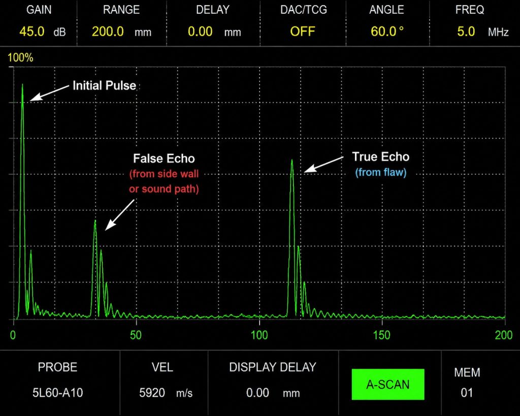
False echoes refer to signals received by radar level meters that are not reflected from the actual material surface. These signals may come from tank walls, agitators, heating coils, welds, flanges, ladders, and other obstacles inside the tank, or may be generated due to medium characteristics, operating conditions, or improper installation positions. False echoes interfere with true echo signals, causing the instrument to misjudge the level height, seriously affecting measurement accuracy and reliability.
Under normal circumstances, radar waves are emitted vertically downward, reflected back upon encountering the material surface, and the instrument calculates the level height based on the time difference between emission and reception. However, when radar waves encounter metal components inside the tank, turbulent surfaces, foam layers, or multiphase media, multiple reflections, scattering, or refraction occur, forming false echo signals.
Common Types of False Echoes
1. Fixed False Echoes
Fixed false echoes originate from fixed metal components inside the tank, such as:
- Tank wall reflections: Reflection signals generated when the edge of the radar beam hits the tank wall
- Agitator blades: Metal blades of stirring equipment produce strong reflections
- Heating coils: Steam heating coils, electric heating tubes, and other metal components
- Waveguide tube inner walls: When installed inside waveguide tubes, welds and uneven surfaces on the tube wall produce reflections
- Installation flanges: Flange edges near the installation port
- Support beams and ladders: Structural support components inside the tank
The characteristic of fixed false echoes is that their position remains unchanged and signal strength is relatively stable, which can be shielded through the instrument’s false echo suppression function.
2. Dynamic False Echoes
The position and intensity of dynamic false echoes change with operating conditions:
- Foam layer reflections: Foam generated on the liquid surface forms an unstable reflection interface
- Turbulent surfaces: Violent liquid surface fluctuations during stirring, feeding, or discharging
- Multiple reflections: Radar waves reflecting multiple times between the material surface and tank wall
- Steam and dust: Steam in high-temperature conditions or dust in powder silos
- Crystallization and buildup: Crystallization and buildup on the antenna surface or tank wall change reflection characteristics
- Phase change processes: Interface changes generated during material condensation, evaporation, and crystallization processes
Dynamic false echoes are more difficult to handle and require selecting appropriate measurement modes and parameter settings based on specific operating conditions.
3. Multipath Effect Echoes
In certain tank configurations, radar waves return to the antenna after multiple reflections:
- Conical bottom tanks: Conical bottoms cause multiple refractions of radar waves
- Spherical tanks: Spherical surfaces cause radar wave scattering
- Small diameter tanks: When the tank diameter is less than 4 times the beam angle distance, multiple tank wall reflections easily occur
Types of Complex Operating Conditions and Challenges
High Temperature and High Pressure Conditions
In high-temperature and high-pressure environments (such as hydrogenation reactors and polymerization kettles), radar level meters face:
- Temperature resistance limits of antenna materials
- Scattering and absorption of radar waves by high-temperature steam
- Changes in dielectric constant with temperature
- Antenna contamination caused by seal aging
Solution strategies: Select high-temperature resistant antennas (such as ceramic antennas, which can withstand temperatures above 400°C), use high-frequency radar (26GHz or higher), use extension tubes or waveguides for heat insulation, and set reasonable temperature compensation parameters.
Strong Corrosive Media
Strong corrosive media such as sulfuric acid, hydrochloric acid, and hydrofluoric acid will:
- Corrode the antenna surface, changing reflection characteristics
- Form crystallization and buildup on the antenna surface
- Corrode internal tank components, increasing false echo sources
Solution strategies: Select PTFE or ceramic material antennas, perform regular cleaning and maintenance, add antenna protection measures, and use non-contact cleaning devices.
Low Dielectric Constant Media
Low dielectric constant media (ε<2) such as liquefied gas, light hydrocarbons, and pure solvents have weak reflection signals:
- True echo signals are weak and easily covered by false echoes
- Low signal-to-noise ratio, unstable measurement
- Require higher transmission power and sensitivity
Solution strategies: Use large-diameter horn antennas or parabolic antennas to improve gain; use high-frequency radar (80GHz) with shorter wavelengths for better reflection on low dielectric constant media; enable maximum sensitivity mode; use guided wave radar when possible.
Dust and Steam Conditions
In equipment such as cement silos, fly ash silos, and evaporators:
- Dust forms a suspended layer in space, producing false echoes
- High-temperature steam absorbs and scatters radar waves
- Dust adheres to the antenna surface, reducing signal strength
Solution strategies: Install purging devices (compressed air or nitrogen) to regularly clean the antenna; select antenna structures with dust covers; use pulsed radar with stronger penetration capability; use high-frequency radar to reduce diffraction effects.
Stirring and Turbulent Conditions
Vessels with stirring equipment such as reactors and blending tanks:
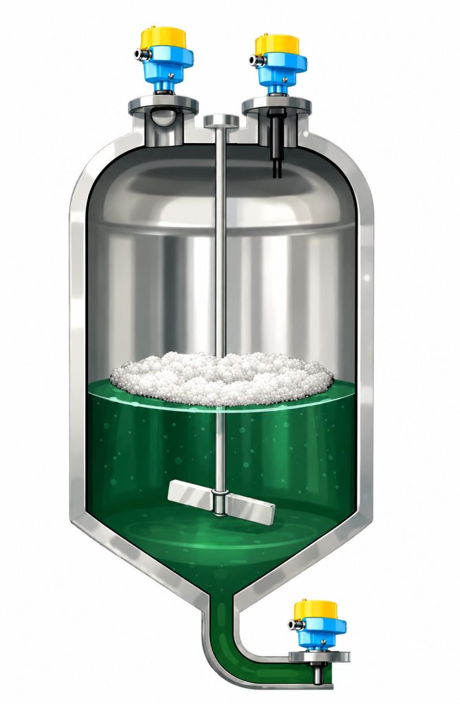
- Agitator blades produce strong fixed false echoes
- Liquid surface fluctuates violently, true echo is unstable
- Vortexes and bubbles are generated during feeding and discharging
Solution strategies: Install off-center to avoid the main influence area of the agitator; use the false echo learning function to record and shield agitator echoes; use averaging algorithms to smooth data fluctuations; select antennas with smaller beam angles to reduce the possibility of the agitator entering the beam range.
Foam Conditions
Fermentation tanks, flotation tanks, washing towers, etc., generate large amounts of foam:
- Foam layer forms a false liquid level interface
- Uneven foam density, unstable echo signal
- Foam height changes rapidly, difficult to track true liquid level
Solution strategies: Use low-frequency radar (6GHz) with strong foam penetration capability; use guided wave radar with waveguide rods that can penetrate the foam layer; enable foam suppression mode to automatically identify and ignore foam echoes; use pressure transmitters for dual measurement verification.
Design Principles for Avoiding False Echoes
Correct Selection
Select the appropriate radar type according to operating condition characteristics:
Frequency selection:
- 6GHz low-frequency radar: suitable for foam, steam, and dust conditions with strong penetration capability
- 26GHz high-frequency radar: general purpose, balancing penetration and accuracy, widely applicable
- 80GHz ultra-high-frequency radar: small beam angle (3°), high accuracy, suitable for small tanks and low dielectric constant media
Antenna types:
- Horn antenna: most commonly used, beam angle 8-10°
- Parabolic antenna: smaller beam angle (4-6°), good focusing, suitable for large tanks and complex conditions
- Rod antenna: suitable for small tanks and installation inside waveguide tubes
- Planar antenna: resistant to high temperature and high pressure, suitable for process flange installation
Measurement principles:
- Pulsed radar (FMCW): high accuracy, suitable for most operating conditions
- Guided wave radar (TDR): unaffected by dielectric constant, suitable for foam, low dielectric, and stirring conditions
- Frequency modulated continuous wave radar: fast dynamic response, suitable for rapidly changing conditions
Optimized Installation Position
Installation position directly affects the generation of false echoes:
Basic principles:
- Distance from tank wall at least 200-300mm to avoid beam edges hitting the tank wall
- Avoid directly below inlet, outlet, and overflow ports
- Stay away from obstacles such as agitators, heating coils, and thermometer wells
- In conical bottom tanks, install as much as possible at the center of the cone top plane
- Spherical tanks should be installed at the highest point at the top
Multiple antenna arrangement:
For extra-large storage tanks (diameter >30m), multiple radars can be used for redundant measurement, selecting the most reliable data through algorithms or taking average values.
Using waveguide tubes or stilling wells:
Under complex operating conditions, waveguide tubes (bypass pipes) can be installed with the radar antenna placed inside the tube to isolate interference sources inside the tank. The inner diameter of the waveguide tube should be ≥150mm, with a smooth surface and no welds or irregularities.
Reasonable Mechanical Structure Design
Connection flanges:
- Use standard flanges (DN80 or above) to ensure sufficient installation space
- Flange face should be horizontal and perpendicular to the antenna axis
- Avoid using excessively long extension tubes to prevent forming resonant cavities
Antenna protection:
- Use insulation flanges or extension tubes for high-temperature conditions
- Add PTFE protective coating for corrosive conditions
- Install purging devices or dust covers for dusty conditions
Grounding:
Good grounding can reduce electromagnetic interference and improve measurement stability. The instrument housing, flange, and tank body should be reliably connected with grounding resistance <4Ω.
Instrument Parameter Configuration and Commissioning
False Echo Suppression Function
Modern radar level meters all have false echo suppression functions that identify and shield false echoes through software algorithms:
False Echo Learning (False Echo Storage):
In an empty tank state or known level state, run the false echo learning program. The instrument will record the position and intensity of all fixed obstacles and automatically shield these signals in subsequent measurements. It is recommended to re-execute learning before equipment commissioning, after major repairs, and after operating condition changes.
Echo Envelope Analysis:
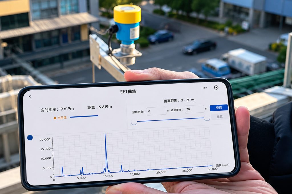
The instrument displays the complete echo curve, allowing engineers to visually identify true and false echoes. True echoes typically have the largest amplitude and regular shape; false echoes have fixed or abnormal positions.
Manual Shielding Zone Settings:
For obstacles at known positions, shielding zones can be manually set, and the instrument will ignore all echo signals within that distance range.
Measurement Mode Selection
Select the appropriate measurement mode according to operating conditions:
Standard mode: suitable for calm liquid surfaces with strong reflection signals
Stirring mode: enhances tracking capability for fluctuating liquid surfaces, using more complex signal processing algorithms
Low dielectric constant mode: improves sensitivity to capture weak reflection signals
Foam mode: automatically identifies and penetrates foam layers
Dust mode: extends echo sampling time to filter out dust interference
Maximum reflection mode: always tracks the strongest echo, suitable for solid level measurement
Signal Processing Parameter Optimization
Damping Time:
Time constant for smoothing output signals, typically set to 3-30 seconds. Increase damping appropriately for turbulent conditions; reduce damping for fast response conditions.
Tracking Speed:
Instrument response speed when level changes. Fast feeding and rapid discharge conditions require high tracking speed; stable conditions can reduce tracking speed to improve stability.
Minimum Reflection Threshold:
Minimum signal strength for the instrument to identify valid echoes. Low dielectric constant media need to lower the threshold to improve sensitivity; strong interference conditions can raise the threshold to filter weak false echoes.
Measuring Range Settings:
Set reasonable upper and lower measurement limits, excluding areas where level cannot appear, reducing false echo interference. For example, below 200mm from the tank bottom and above 500mm from the tank top can be set as invalid areas.
Advanced Technical Means
Intelligent Signal Processing Algorithms
New generation radar level meters adopt advanced digital signal processing technology:
Adaptive filtering: automatically adjusts filtering parameters according to real-time signal characteristics
Fuzzy logic: identifies true echoes through multi-dimensional judgment (amplitude, position, rate of change, etc.)
Neural networks: learns echo characteristics of specific operating conditions to improve recognition accuracy
Multi-echo tracking: simultaneously monitors multiple echoes, automatically switching when the main echo is abnormal
Multi-sensor Fusion
Under extremely complex operating conditions, multiple measurement principles can be combined:
Radar + pressure transmitter: radar measures main level, pressure transmitter verifies
Radar + ultrasonic: mutually redundant, improving reliability
Radar + weighing system: calculates level from material weight for cross-verification
Remote Diagnosis and Maintenance
Modern intelligent radar level meters support:
Remote echo waveform viewing: upload echo curves to host computer via HART, Modbus, Profibus, etc., for remote analysis by engineers
Device health monitoring: monitors antenna contamination, circuit faults, signal quality degradation, and other abnormalities
Predictive maintenance: predicts maintenance timing based on device operating data to avoid sudden failures
Actual Case Analysis
Case 1: False Echo Problem in Large Crude Oil Storage Tank
Operating condition description:
Floating roof tank with 40m diameter and 20m height, storing crude oil, level change range 2-18m, multiple heating coils and thermometer wells inside the tank.
Problem phenomenon:
Radar level meter frequently jumps, sometimes displays fixed at around 8m, differing 1-2m from manual gauging.
Analysis process:
Viewing the echo curve revealed three strong false echoes at 8m, 12m, and 15m, corresponding to heating coils, support beams, and thermometer wells inside the tank. When the true level approached these positions, false echoes covered the true echo.
Solution:
- Moved radar from tank center to 3m from center position to avoid main obstacles
- Executed false echo learning to shield known obstacles
- Adjusted to stirring mode (although no agitator, this mode has stronger echo recognition algorithm)
- Set three shielding zones: 7.5-8.5m, 11.5-12.5m, 14.5-15.5m
- Reduced tracking speed, increased damping time to 20 seconds
Result:
Measurement stability significantly improved, error with manual gauging controlled within ±10mm.
Case 2: Foam Interference in Fermentation Tank
Operating condition description:
Biopharmaceutical fermentation tank, 8m high, 3m diameter, liquid level 4-7m, with 1-1.5m thick foam layer on top.
Problem phenomenon:
Radar displays liquid level 1-1.5m higher, actually measuring foam surface rather than liquid surface.
Solution:
- Replaced with 6GHz low-frequency radar with stronger foam penetration capability
- Enabled foam suppression mode
- Installed guided wave radar (cable type), waveguide cable reaches directly to liquid bottom, foam has minimal effect on guided wave radar
- Combined with pressure transmitter to measure tank bottom pressure, calculate level for comparison
Result:
Guided wave radar solution completely solved the problem, measurement accuracy ±5mm, unaffected by foam.
Case 3: High-Temperature Fly Ash Silo
Operating condition description:
Fly ash storage silo 30m high, 10m diameter, temperature 150-200°C, serious dust.
Problem phenomenon:
Dust accumulation on antenna surface, measurement distance gradually shortened, requiring manual antenna cleaning every 2-3 weeks.
Solution:
- Added automatic purging device, automatically purging for 30 seconds every hour
- Selected ceramic antenna, resistant to high temperature and less prone to dust adhesion
- Installed insulation flange to reduce temperature at antenna
- Used 26GHz radar with small beam angle to reduce dust scattering effects
Result:
Cleaning cycle extended to 6 months, measurement stable and reliable.
Maintenance and Care Recommendations
Regular Inspection Items
Monthly inspection:
- Antenna surface cleanliness, presence of buildup, crystallization, dust
- Whether flange connections are loose or leaking
- Whether instrument display is normal, presence of alarms
- Compare with manual gauging or other instruments to confirm measurement accuracy
Quarterly inspection:
- View echo curves, analyze false echo changes
- Check whether grounding is good
- Check wiring terminals to prevent corrosion and loosening
- Clean antenna surface
Annual inspection:
- Re-execute false echo learning
- Verify measurement accuracy
- Check seals, replace if necessary
- Backup software parameters
Common Troubleshooting
Display “No Echo”:
- Check if level exceeds measurement range
- Whether antenna is completely covered (buildup, dust)
- Whether dielectric constant is too low, echo too weak
- Whether threshold setting is too high
Measurement Jumping:
- False echo interference, need to relearn or set shielding zones
- Liquid surface fluctuates violently, increase damping time
- Foam interference, enable foam suppression mode
Measurement Deviation:
- Antenna contamination, needs cleaning
- Poor installation position, off-center or with obstacles
- Dielectric constant change, needs recalibration
- Incorrect tank type parameter settings
Future Development Trends
Higher Frequency Radar
120GHz and 240GHz radars are under development, with beam angles reaching 1-2°, almost unaffected by obstacles inside the tank, measurement accuracy up to ±0.5mm.
Artificial Intelligence Applications
Machine learning-based echo recognition algorithms can automatically adapt to operating condition changes without manual parameter adjustment.
Internet of Things Integration
Radar level meters will be deeply integrated into the Industrial Internet of Things, achieving cloud data analysis, remote diagnosis, and predictive maintenance.
Multifunctional Integration
Future radar level meters may integrate temperature, pressure, and density measurement functions, becoming multi-parameter measuring instruments.
Conclusion
The false echo problem of radar level meters under complex operating conditions requires systematic management throughout the entire life cycle from selection, installation, commissioning, and maintenance. Correctly understanding the generation mechanism of false echoes, reasonably selecting radar types and antenna structures, optimizing installation positions, making full use of instrument intelligent functions, and combining with regular maintenance can effectively avoid false echo interference and achieve accurate and reliable level measurement.
With technological progress, the anti-interference capability and intelligence level of radar level meters continue to improve, allowing stable operation even under more complex and extreme operating conditions. Engineers should continue learning new technologies, accumulating practical experience, and providing reliable level measurement solutions for industrial production.

