
Introduction
Saline solution is a common process medium in pharmaceutical manufacturing, medical consumables production, medical device cleaning, and liquid preparation systems. Although saline has good fluidity and may appear relatively easy to measure, actual production environments place strict requirements on the stability, cleanability, corrosion resistance, and alarm reliability of level instruments.
This is especially important for saline preparation tanks, buffer tanks, and temporary storage tanks. Inaccurate level measurement may result in tank overflow, dry running of transfer pumps, incorrect batch volumes, or interruptions in downstream production.

A medical consumables manufacturer needed to install a continuous level monitoring system on a saline temporary storage tank as part of an expansion project. After evaluating the operating conditions and control requirements, the company selected a side-mounted 316L stainless steel magnetic level indicator equipped with a 4–20 mA remote transmitter and high- and low-level magnetic switches.
The final solution provided three functions: direct local indication, remote monitoring in the control room, and independent level alarm and interlock protection.
1. Level Monitoring Requirements for the Saline Storage Tank
The storage tank was mainly used to temporarily hold prepared 0.9% sodium chloride solution. The tank had a vertical structure. During production, saline entered the tank from the upstream preparation system and was then transferred through a bottom outlet to downstream processing units.
The project had several requirements for the level measurement system.
First, operators needed to observe the tank level directly at the installation site. Even during a temporary power failure, the instrument had to continue providing a clear local indication so that inspection personnel could determine how much liquid remained in the tank.
Second, the continuous level signal needed to be transmitted to the programmable logic controller, or PLC. The control system would use the real-time level signal to regulate the inlet valve and transfer pump. It would also display the tank level and historical level trend on the central control interface.
Third, the tank required both high-level and low-level alarms. The high-level alarm was intended to prevent overflow caused by continued filling. The low-level alarm was required to protect the transfer pump from prolonged operation without sufficient liquid.
In addition, all wetted components had to be selected according to the characteristics of saline, the cleaning process, and the sanitary requirements of the production system. The instrument structure also had to support convenient drainage and maintenance while minimizing areas in which liquid could remain for extended periods.
2. Challenges in Measuring Saline Solution Levels
Saline solution mainly consists of water and sodium chloride. Its density is close to that of water, and its viscosity is relatively low. From the perspective of buoyancy-based measurement, saline is generally suitable for a magnetic level indicator.
However, saline contains chloride ions. Therefore, careful attention must still be paid to the material and surface treatment of the wetted components.
If ordinary carbon steel is used for components in direct contact with saline, corrosion may occur after extended operation. This can shorten the service life of the instrument and negatively affect the sanitary condition of the production system.
Even when stainless steel is selected, its suitability should be evaluated according to the saline concentration, operating temperature, cleaning chemicals, exposure time, and process conditions. For low-concentration saline at ambient temperature, 316L stainless steel is generally more suitable than conventional 304 stainless steel for wetted components.
Cleanability is another important consideration. Conventional side-mounted structures may be suitable for general process water, cleaning saline, or applications outside the final sterile production stage, provided that they meet the actual production requirements.
However, when the instrument comes into direct contact with a final sterile product, additional factors must be considered. These may include hygienic process connections, internal surface roughness, passivation treatment, gasket materials, drainability, clean-in-place compatibility, sterilization requirements, and validation procedures.
An instrument should not be assumed to be suitable for sterile production solely because its wetted parts are made of stainless steel.
For this project, the application boundary was clearly defined during the selection stage. The magnetic level indicator was installed in the saline temporary storage and transfer section for process level monitoring. The wetted components were treated and maintained according to the manufacturer’s internal cleaning procedures.
3. Why a Magnetic Level Indicator Was Selected
A magnetic level indicator operates according to the principles of communicating vessels and magnetic coupling.
The measuring chamber is connected to the storage tank through upper and lower process connections. As a result, the liquid level inside the chamber remains consistent with the liquid level in the tank.
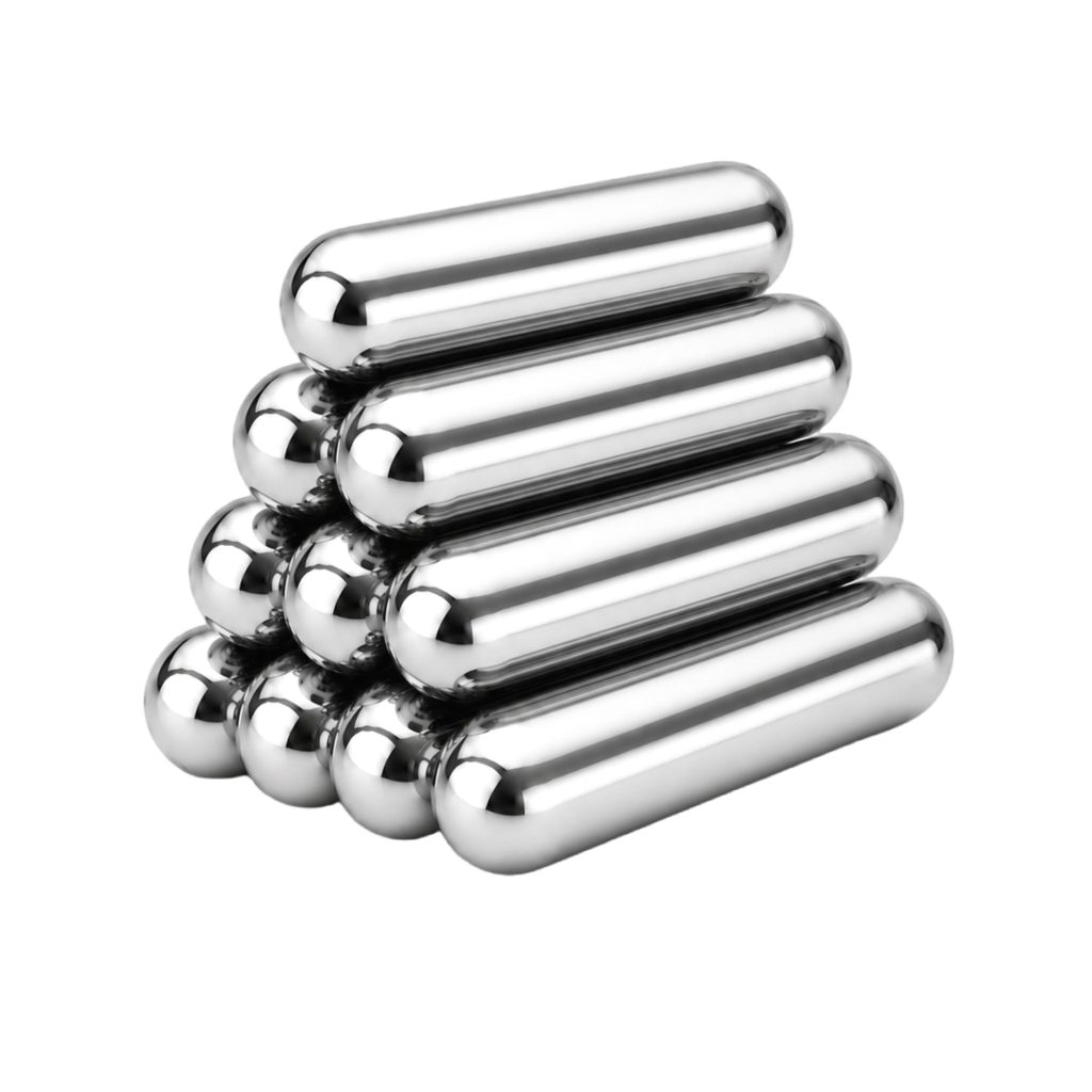
A magnetic float inside the chamber rises and falls with the liquid level. The magnetic field of the float activates the external bicolor flaps. The boundary between the two colors represents the current liquid level.
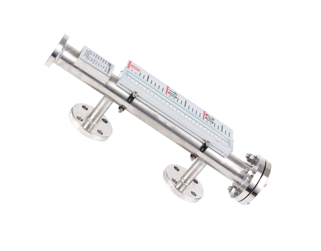
This measurement principle was suitable for the saline storage tank for several reasons.
3.1 Local Indication Without External Power
The flap indication system does not require an external power supply. Even if the PLC, display unit, or plant power supply becomes unavailable, operators can still read the tank level from the magnetic flaps and scale.
This provides a reliable local reference during routine inspection, commissioning, shutdown, or control system failure.
3.2 Separation Between the Indicator and the Process Medium
The float is contained inside the sealed measuring chamber, while the magnetic flap indicator is mounted externally.
Operators do not need to observe the saline through a transparent glass tube. This arrangement reduces the potential risks associated with breakage, direct leakage, and contamination of transparent level gauges.
3.3 Suitability for Low-Viscosity Saline
Saline has good fluidity and does not normally cause float sticking under standard operating conditions.
Standard magnetic level indicators are available for a wide range of medium densities. The density of 0.9% saline is within the normal operating range of this type of instrument and provides sufficient buoyancy for stable float movement.
3.4 Local Display and Remote Monitoring in One System
By installing a reed-chain remote transmitter, the magnetic level indicator can convert the float position into a standard 4–20 mA output signal.
This signal can be connected to a PLC, distributed control system, digital indicator, or data acquisition system. Magnetic switches can also be added to provide high-level, low-level, or high-high-level alarms.
Therefore, one instrument assembly can provide local indication, continuous remote measurement, alarm switching, and process interlock functions.
3.5 Convenient Maintenance
Isolation valves were installed between the magnetic level indicator and the storage tank.
Under suitable operating conditions, maintenance personnel can isolate the measuring chamber from the main tank, drain the saline from the chamber, and perform cleaning or inspection without removing the entire tank level monitoring system.
This arrangement improves maintainability and reduces production downtime.
4. Selection of the Magnetic Level Indicator
Based on the tank dimensions, saline properties, and process control requirements, the project selected a standard side-mounted magnetic level indicator with 316L stainless steel wetted parts.
4.1 Wetted Material
The measuring chamber and major wetted components were manufactured from 316L stainless steel.
Compared with ordinary stainless steel and carbon steel, 316L offers better suitability for low-concentration saline at ambient temperature. During manufacturing and acceptance inspection, attention was also given to weld quality, internal surface treatment, and gasket compatibility.
For applications with more demanding cleanliness requirements, optional treatments may include internal polishing, pickling, passivation, and hygienic sealing materials.
If the saline temperature is elevated, the chloride concentration is higher, or chlorine-containing cleaning chemicals are used, the suitability of the material must be reassessed. More corrosion-resistant materials or alternative instrument structures may be required under severe chloride conditions.
4.2 Measuring Range
The measuring range of a side-mounted magnetic level indicator is normally determined by the center-to-center distance between the upper and lower process connections. It should not simply be assumed to be equal to the total height of the tank.
During selection, the normal operating level, maximum liquid level, minimum liquid level, alarm points, and instrument blind zones should all be confirmed.
The effective indication range should cover the portion of the tank required for filling, storage, and transfer operations.
A single measuring chamber can cover most small and medium-sized storage tanks. For taller tanks, a segmented structure may be used. In such installations, the sections and process connections must be accurately aligned to prevent chamber distortion, restricted float movement, or discontinuous level indication.
4.3 Measurement Accuracy
The required resolution and accuracy were selected according to the process control objective.
A saline temporary storage tank is generally not used as a high-accuracy custody transfer or batch metering device. Its level instrument is mainly used for inventory awareness, filling control, pump protection, and alarm management.
Therefore, the instrument selection should balance accuracy, reliability, cost, and maintenance requirements.
It is also important to recognize that a magnetic level indicator measures liquid height rather than liquid volume.
When the actual volume inside the tank must be displayed, the control system should use a tank-strapping table or a mathematical relationship based on the tank geometry. The level percentage cannot always be treated as identical to the volume percentage, especially for horizontal cylindrical tanks, conical-bottom tanks, or irregularly shaped vessels.
4.4 Remote Transmission Output
The magnetic level indicator was equipped with a reed-chain remote transmitter that converted the liquid level into a 4–20 mA current signal.
After the measuring range was configured in the PLC, the control system could display the liquid level in engineering units and as a percentage. It could also record the changes occurring during filling, holding, and discharge operations.
The continuous level signal was used as part of the inlet valve control logic. When the liquid reached the predetermined filling limit, the PLC issued a command to stop the filling process.
This reduced reliance on manual observation and manual valve operation.
4.5 High- and Low-Level Alarms
A high-level magnetic switch and a low-level magnetic switch were installed on the outside of the measuring chamber.
The high-level switch was used to close the inlet valve and activate an audible or visual alarm. The low-level switch was used to stop the transfer pump or indicate that the tank required refilling.
These magnetic switches provided independent switching protection.
Even if the continuous 4–20 mA signal became abnormal because of a wiring fault, transmitter failure, or control system problem, the high- and low-level switches could still provide an additional layer of protection.
This configuration improved the overall safety and reliability of the tank level control system.
5. Installation and Commissioning
The performance of a magnetic level indicator depends not only on the instrument itself but also on the quality of the installation.
Before installation, the technical team verified the center-to-center distance of the tank connections, flange specifications, measuring range, pressure rating, gasket material, and float orientation.
When the float was inserted into the measuring chamber, the marked end was positioned according to the installation instructions. An incorrectly installed float may fail to rise properly or may produce an incorrect magnetic response.
The magnetic level indicator was connected to the storage tank through upper and lower process pipes. The main chamber was installed vertically.
Isolation valves were installed between the tank and the level indicator. A drain and flushing connection was provided at the bottom of the chamber to support cleaning and maintenance.
The installation position was selected away from severe mechanical vibration. Ferromagnetic clamps, steel supports, and other magnetic materials were also kept at a suitable distance from the chamber and flap indicator.
Objects made from magnetic materials can interfere with the magnetic coupling between the float and the external display or alarm switches.
After the wiring was completed, a calibration magnet was used to reset the flaps to their correct initial position.
The zero point and full-scale output of the 4–20 mA transmitter were then checked. The corresponding liquid-level range was configured in the PLC.
When saline was introduced into the tank for commissioning, the upper isolation valve was opened first. The lower valve was then opened slowly to allow the saline to enter the measuring chamber in a controlled manner.
Opening the lower valve too quickly could expose the float to a sudden hydraulic impact. This might cause the float to move rapidly and result in temporary flap indication disorder.
Three main verification procedures were completed during commissioning.
The first was to compare the magnetic level indication with a known tank level.
The second was to confirm that the level displayed in the control room corresponded with the local indication.
The third was to simulate high- and low-level conditions and verify the operation of alarms, inlet valves, transfer pumps, and interlock logic.
6. Operating Results
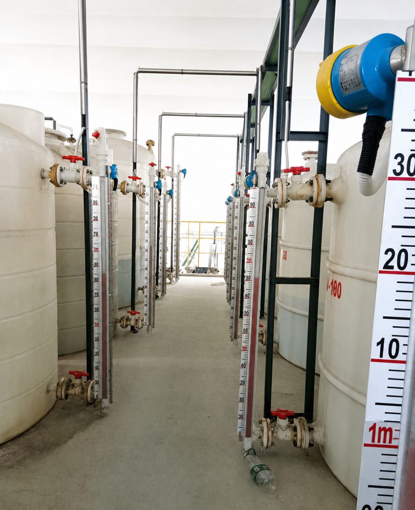
After installation and commissioning, the magnetic level indicator provided stable continuous level indication on the saline temporary storage tank.
Operators could identify the current liquid level quickly by observing the boundary between the two flap colors. They no longer needed to inspect the liquid through a tank opening or rely on indirect methods to estimate the amount of saline remaining.
The control room received the 4–20 mA level signal continuously. Operators could monitor the real-time level, review historical trends, and use the data to support filling and transfer operations.
When the liquid reached the high-level alarm point, the control system generated an alarm and stopped further filling. This reduced the risk of saline overflow.
When the liquid level dropped to the low-level set point, the transfer pump was stopped. This prevented the pump from operating under dry or insufficiently lubricated conditions.
The combination of local indication, continuous remote transmission, and independent switch alarms meant that the level monitoring system no longer depended on a single signal source.
Operators could verify the actual liquid level locally while managing the process centrally from the control room. Maintenance personnel could also diagnose signal abnormalities more easily by comparing the local flap indication with the remote output.
7. Maintenance and Cleaning Considerations
Although saline has a low viscosity, small amounts of impurities or salt deposits may accumulate at the bottom of the measuring chamber after extended operation.
A periodic drainage, flushing, and inspection schedule should therefore be established according to the production cycle and process cleanliness requirements.
Before cleaning, the upper and lower isolation valves between the storage tank and magnetic level indicator should be closed.
The chamber must be depressurized before the saline is drained through the bottom connection.
During cleaning, maintenance personnel should confirm that the float moves freely, the drain valve is not blocked, and the flap display changes continuously without missing or incorrectly oriented flaps.
For production systems involving high-temperature sterilization, strong oxidizing cleaning chemicals, or chlorine-containing disinfectants, the resistance of the gaskets, float, and wetted materials must be confirmed during the selection stage.
After cleaning, the zero indication should be checked. The remote output should also be verified against the actual liquid level or another approved reference method.
Ferromagnetic brackets or clamps should not be added casually around the instrument.
If a magnetic switch or remote transmitter is removed during maintenance, it should be returned to its original position. The alarm point and output signal should then be tested again before the system is returned to service.
8. Important Selection Considerations for Saline Level Measurement
When selecting a magnetic level indicator for saline solution, the measuring range and purchase price should not be the only considerations.
The actual saline concentration, operating temperature, and presence of additional chemical components should first be confirmed.
The application stage should also be clearly identified. The requirements may differ considerably depending on whether the instrument is used in a general process section, a cleaning system, an intermediate storage section, or a sterile product-contact application.
The wetted material and sealing materials should be selected according to the chloride environment.
The tank connection positions should be checked against the required level measuring range. The upper and lower blind zones should also be considered.
The need for a 4–20 mA transmitter, high- and low-level magnetic switches, local indication, and process interlock functions should be determined according to the control strategy.
Suitable isolation, drainage, flushing, and maintenance access should be included in the installation design.
When the process has strict requirements for hygienic design, complete drainability, clean-in-place performance, steam sterilization, or validation, a specifically engineered hygienic level measurement solution should be selected.
A conventional industrial storage tank configuration should not be copied directly into a sterile pharmaceutical application without a detailed technical assessment.
Conclusion
This application demonstrates that a 316L stainless steel magnetic level indicator can provide an effective combination of local indication, continuous remote transmission, and high- and low-level alarms for ambient-temperature, low-viscosity saline storage and transfer applications.
By correctly selecting the wetted material, measuring range, signal output, alarm configuration, and installation method, the system can improve the visibility and reliability of saline storage tank level monitoring.
In practical projects, the selection of a magnetic level indicator should also consider saline concentration, operating temperature, tank pressure, cleaning method, hygienic requirements, corrosion conditions, and control objectives.
Only when the instrument configuration is properly matched to the actual process conditions can the saline level monitoring system deliver stable measurement, dependable protection, and convenient long-term maintenance.

