
When configuring a radar level meter, parameters such as low level, high level, measuring range, ullage, and measuring distance can easily cause confusion. This is especially true for engineers or technicians who are setting up a radar level transmitter for the first time.
One of the most common misunderstandings is to assume that the low-level parameter simply means the minimum liquid height measured upward from the bottom of the tank.
In most radar level measurement applications, however, this is not how the parameter is defined.
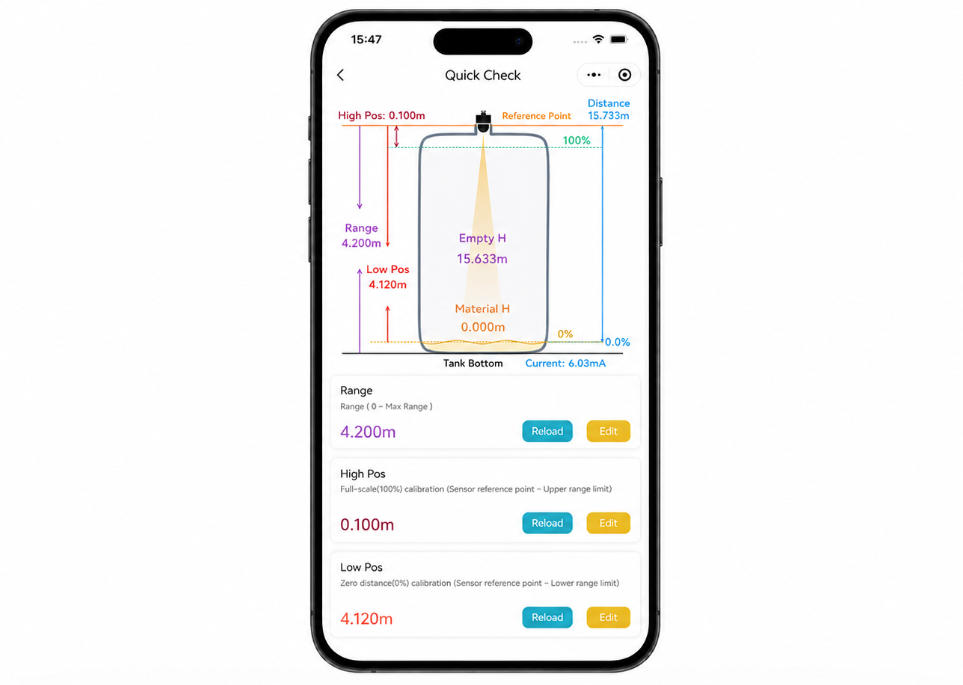
The low-level parameter usually represents the distance from the radar measurement reference point to the position defined as 0% level.
Understanding this principle is essential for correctly configuring a radar level meter.
For example, suppose a storage tank is 6 meters deep and the radar level meter is installed on the top of the tank. If a position near the tank bottom is defined as 0% level, the distance from the radar reference point to that 0% position can be used as the low-level setting.
This also explains an important characteristic of radar level measurement:
The lower the liquid level, the greater the measured distance. The higher the liquid level, the shorter the measured distance.
As a result, the numerical value of the low-level parameter is usually larger than that of the high-level parameter.
What Is the Low-Level Parameter on a Radar Level Meter?
To understand the low-level setting, it is first necessary to understand what a radar level meter actually measures.
A radar level meter does not directly measure the liquid height from the bottom of the tank. Instead, it first measures:
the distance between the radar sensor and the surface of the liquid.
Modern radar level meters, including 80 GHz FMCW radar instruments, transmit high-frequency electromagnetic waves toward the material surface. When the radar signal reaches the liquid or solid surface, part of the signal is reflected back toward the antenna.
The instrument analyzes the reflected signal and calculates the distance between the sensor and the material surface. It then uses the configured high-level and low-level parameters to convert this distance into level height, percentage level, and an analog output such as 4–20 mA.
Therefore, it is useful to imagine the radar measurement system as a vertical coordinate system.
The radar sensor is located at the top.
The liquid surface is below the sensor.
The bottom of the tank is even farther away from the sensor.
Suppose the distance from the radar measurement reference point to the 0% level position is 6.0 meters. The low-level parameter can therefore be set to:
Low Level = 6.0 m
Now suppose the 100% level position is located only 0.5 meters below the radar reference point. The high-level parameter can be set to:
High Level = 0.5 m
Therefore:
Low Level = 6.0 m
High Level = 0.5 m
Although the low-level position is physically located below the high-level position inside the tank, the radar level meter measures distance downward from the top.
This is why:
Low-Level Value > High-Level Value
This is one of the most important concepts to understand when configuring radar level meter parameters.
Is the Low-Level Parameter the Same as the Measuring Range?
No.
The low-level setting and the measuring range may sometimes have similar numerical values, but they serve different purposes.
The measuring range generally defines the area within which the radar level meter searches for and processes reflected radar signals.
The low-level parameter, on the other hand, establishes the position corresponding to 0% level and is used when calculating level height, percentage, and analog output.
A simple comparison can help clarify the difference:
| Parameter | Main Function |
|---|---|
| Measuring Distance | Actual distance from the radar reference point to the current liquid surface |
| Measuring Range | Defines the radar signal processing and measurement area |
| Low Level | Defines the 0% or empty-tank level position |
| High Level | Defines the 100% or full-tank level position |
| Low Level − High Level | Effective level span |
| Level Height | Calculated from the low-level setting and current measuring distance |
In a simple vertical storage tank, the low-level value may be close to the maximum measuring distance because the 0% position is often located close to the tank bottom.
However, similar numerical values do not mean that the two parameters are technically identical.
Where Should the Low-Level Measurement Start?
Before calculating the low-level setting, the measurement reference point must be identified.
This is extremely important because all distance-related parameters depend on the same reference point.
Depending on the radar level meter design, the measurement reference point may be located at the process connection, mounting flange, antenna reference plane, or another specified point on the instrument.
Therefore, the correct low-level value is not necessarily the same as the nominal height of the tank.
For example, suppose the internal tank height from the top mounting flange to the bottom is 7.0 meters.
If the actual radar measurement reference point extends 0.2 meters below the flange, entering 7.0 meters directly as the low-level value may introduce a measurement offset of approximately 0.2 meters.
The correct question is therefore not:
“How tall is the tank?”
Instead, the engineer should determine:
What is the vertical distance from the radar measurement reference point to the position defined as 0% level?
That distance is the correct basis for the low-level parameter.
How Do You Calculate the Low-Level Setting of a Radar Level Meter?
Assume:
L = Low-level distance
D = Current measured distance from the radar to the liquid surface
H = Current liquid level height
The basic radar level calculation is:
H = L − D
In other words:
Liquid Level Height = Low-Level Distance − Current Measured Distance
This is one of the most useful formulas for understanding radar level measurement.
Example
Suppose the low-level parameter is set to:
L = 5.5 m
The radar currently measures the liquid surface at:
D = 2.0 m
The liquid level height is therefore:
H = 5.5 − 2.0
H = 3.5 m
The current liquid level is 3.5 meters.
Now assume the liquid level drops and the radar measures:
D = 4.5 m
Then:
H = 5.5 − 4.5
H = 1.0 m
The liquid level is now only 1.0 meter.
This example demonstrates the inverse relationship between radar measuring distance and liquid level:
As the liquid level rises, the measured distance decreases.
As the liquid level falls, the measured distance increases.
How Do You Calculate Level When Both High Level and Low Level Are Configured?
In most industrial tanks, the maximum operating level does not extend all the way to the radar sensor.
A safety clearance is normally maintained between the maximum liquid level and the antenna.
Suppose the distance from the radar reference point to the 0% position is:
Low Level L = 5.8 m
The 100% operating level is located 0.5 meters below the radar reference point:
High Level A = 0.5 m
The effective measurement span is:
S = L − A
Therefore:
S = 5.8 − 0.5
S = 5.3 m
The effective 0–100% liquid-level range is therefore 5.3 meters.
Now suppose the current measuring distance is:
D = 2.1 m
The current liquid level height is:
H = 5.8 − 2.1
H = 3.7 m
To calculate the percentage level, use:
P = (L − D) ÷ (L − A) × 100%
Substituting the values:
P = (5.8 − 2.1) ÷ (5.8 − 0.5) × 100%
P ≈ 69.8%
The tank is therefore approximately 69.8% full.
This formula is particularly useful when checking whether the radar level meter, PLC, or DCS is scaling the signal correctly.
What Is the Relationship Between Low Level and the 4–20 mA Output?
Radar level meters are commonly connected to PLCs, DCS systems, process controllers, or remote displays through a 4–20 mA analog signal.
Under normal 4–20 mA scaling:
0% level = 4 mA
100% level = 20 mA
The low-level and high-level settings establish these two reference positions.
For standard forward output:
0% → 4 mA
100% → 20 mA
The analog current can be calculated using:
I = 4 + 16 × P
where P is expressed as a decimal between 0 and 1.
Using the previous example:
P = 69.8% = 0.698
Therefore:
I = 4 + 16 × 0.698
I ≈ 15.17 mA
The PLC or DCS should therefore receive approximately:
15.17 mA
If the instrument is configured for reverse 20–4 mA output, the calculation becomes:
I = 20 − 16 × P
This is why a radar level meter showing lower current as the level rises is not necessarily defective.
The first step should be to check whether the current output has been configured for 20–4 mA reverse mode.
Does the Low-Level Position Always Have to Be at the Bottom of the Tank?
No.
This is another common misunderstanding when setting radar level meter parameters.
The low-level parameter represents the position defined by the user as 0% level. It does not necessarily have to correspond to the physical lowest point of the vessel.
Consider a conical-bottom tank.
The lowest part of the cone may contain residual material, sediment, or an outlet section that is not considered part of the usable process volume.
If the process specification defines a position 0.4 meters above the actual bottom as 0% usable level, the low-level parameter should be based on that process zero point.
It should not automatically be calculated to the lowest point of the cone.
The same principle applies to wastewater tanks.
Suppose a wastewater basin is 8 meters deep, but approximately 0.5 meters at the bottom is permanently occupied by sludge.
If the control system only needs to monitor usable water level above the sludge layer, the 0% level can be defined above the actual tank bottom.
Therefore, determining the correct low-level position should consider three factors:
Measurement reference point
Actual process zero position
Operating and control requirements
The low-level setting should not simply be copied from the maximum measuring range printed in the instrument specifications.
Why Does an Incorrect Low-Level Setting Cause Incorrect Level Readings?
Because the low-level parameter directly participates in the level calculation.
Suppose the actual low-level distance should be:
L = 6.0 m
But the instrument is incorrectly configured as:
L = 5.5 m
If the radar correctly measures the current liquid surface at:
D = 3.0 m
The correct level should be:
H = 6.0 − 3.0
H = 3.0 m
However, with the incorrect configuration:
H = 5.5 − 3.0
H = 2.5 m
The radar distance measurement itself may be completely accurate, but the displayed liquid level will always be approximately 0.5 meters too low.
This is a common troubleshooting situation.
An engineer may inspect the echo curve and find that the radar reflection is stable. The measured distance may also agree with a manual measurement, yet the level shown on the display or PLC remains consistently incorrect.
In this situation, the radar sensor itself may not be the problem.
The following parameters should be checked first:
- Measurement reference point
- Low-level setting
- High-level setting
- Distance offset
- Output scaling
A fixed level error often indicates a configuration or reference-point problem rather than unstable radar measurement.
Common Mistakes When Setting the Low-Level Parameter
Several configuration errors frequently occur during commissioning.
1. Using the Nominal Tank Height Directly as the Low-Level Setting
The nominal tank height does not always equal the distance from the radar reference point to the process 0% position.
Installation nozzles, flanges, antenna extensions, internal tank structures, and process dead zones can all affect the actual reference distance.
2. Interpreting Low Level as the Minimum Liquid Height
This is perhaps the most common misunderstanding.
A radar level meter normally works with a downward distance coordinate system.
Therefore, the low-level setting is usually a relatively large distance measured from the sensor toward the bottom of the tank.
3. Confusing Low Level With Measuring Range
The measuring range defines the area within which the instrument performs measurement and signal processing.
The high-level and low-level settings define the scaling relationship used for calculating level percentage and output signals.
They are related, but they are not the same parameter.
4. Ignoring the Measurement Reference Point
The mounting flange, process connection, antenna tip, and internal radar reference point may not be located at exactly the same position.
Even an error of several centimeters can become noticeable in applications that require high measurement accuracy.
For precise level measurement, the correct reference point must always be confirmed before entering the high-level and low-level parameters.
How to Set the Low-Level Parameter Correctly
For a typical storage tank, the configuration process can be simplified into several logical steps.
First, identify the measurement reference point specified for the radar level meter.
Next, measure the vertical distance from this reference point to the desired 0% liquid-level position. Use this distance as the basis for the low-level setting.
Then determine the desired 100% operating level and measure the distance from the same reference point to this position. Use this value as the high-level setting.
After that, confirm that the configured radar measuring range covers the entire required measurement area.
Also make sure that the maximum operating level does not enter a region where the radar cannot measure reliably.
Once configuration is complete, verify the measurement using an empty-tank condition, a known liquid level, manual gauging, or another reliable reference measurement.
A useful troubleshooting rule is:
If the measured radar distance is correct but the calculated liquid level is wrong, check the low-level, high-level, reference-point, and offset settings.
However:
If the measured radar distance itself is unstable or incorrect, investigate installation and echo conditions.
Possible causes may include:
- Tank-wall reflections
- Internal ladders or support structures
- Agitators
- Filling streams
- Nozzles
- Foam
- Condensation
- Steam or vapor
- Material buildup on the antenna
- Strong false echoes
In difficult applications, correct installation and false-echo suppression or echo-learning functions may be required.
Radar Level Meter Low-Level Calculation Example
Consider a tank with the following configuration:
Measurement reference point to 0% level:
Low Level = 7.2 m
Measurement reference point to 100% level:
High Level = 0.7 m
Current radar measured distance:
D = 3.4 m
First calculate the current level height:
H = L − D
H = 7.2 − 3.4
H = 3.8 m
Next calculate the effective measurement span:
S = L − A
S = 7.2 − 0.7
S = 6.5 m
Then calculate the level percentage:
P = (L − D) ÷ (L − A) × 100%
P = (7.2 − 3.4) ÷ 6.5 × 100%
P ≈ 58.5%
Therefore, the tank is approximately:
58.5% full
For standard 4–20 mA output:
I = 4 + 16 × 0.585
I ≈ 13.36 mA
The expected analog output is therefore approximately:
13.36 mA
This type of manual calculation is very useful during commissioning because it allows technicians to compare the radar display, PLC value, and measured current signal.
Low-Level, High-Level, Distance, and Level: A Simple Way to Remember Them
A simple way to remember the relationship is to think from the radar sensor downward.
The radar measures distance from the top.
The 100% level is relatively close to the radar, so the high-level distance is small.
The 0% level is farther away from the radar, so the low-level distance is large.
Therefore:
High liquid level = short radar distance
Low liquid level = long radar distance
And in most standard configurations:
Low-Level Distance > High-Level Distance
The main level calculation is:
Liquid Level = Low Level − Current Distance
The level percentage is:
Level % = (Low Level − Current Distance) ÷ (Low Level − High Level) × 100%
For standard 4–20 mA output:
Current = 4 + 16 × Level Fraction
Once these three relationships are understood, most radar level meter parameter settings become much easier to interpret.
Conclusion: Understanding the Low-Level Parameter Is the Key to Correct Radar Level Measurement
The low-level parameter of a radar level meter is not simply the height of the tank, nor is it automatically equal to the maximum measuring range.
In most applications:
Low Level = Distance from the Radar Measurement Reference Point to the 0% Level Position
The basic liquid-level calculation is:
Liquid Level Height = Low Level − Current Radar Distance
When both high level and low level are configured:
Level Percentage = (Low Level − Current Distance) ÷ (Low Level − High Level) × 100%
The most important concept is the direction of measurement.
Radar level meters measure downward from the sensor. Therefore, a low liquid level produces a larger measured distance, while a high liquid level produces a smaller measured distance.
During commissioning, technicians should first identify the correct measurement reference point, then determine the process 0% and 100% positions, and finally configure the measuring range and output scaling.
When these parameters are configured correctly, the radar level meter display, 4–20 mA signal, and PLC or DCS level indication can remain consistent with the actual process level.

