
1. What Is a Remote Transmitter?
A remote transmitter is an industrial measuring instrument that transfers process pressure or differential pressure to a transmitter sensing element through a remote diaphragm seal, capillary tube, and filling fluid.
It is commonly used for measuring process media that are:
- Hot;
- Highly corrosive;
- Highly viscous;
- Easy to crystallize;
- Easy to solidify;
- Likely to clog conventional impulse lines;
- Subject to strict hygienic requirements.
A conventional pressure transmitter is usually mounted directly at or close to the pressure tapping point. In many installations, the process medium comes into direct contact with the pressure-sensing components of the instrument.
A remote transmitter works differently. A flexible isolation diaphragm separates the transmitter from the process medium. Pressure applied to the diaphragm is transferred through a sealed filling fluid to the sensing element inside the transmitter.
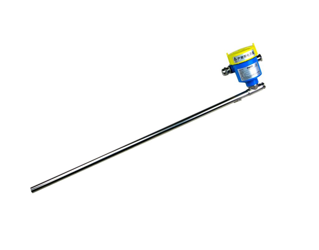
Remote transmitters are widely used in industries such as:
- Oil and gas;
- Petrochemical processing;
- Chemical manufacturing;
- Power generation;
- Pharmaceutical production;
- Food and beverage processing;
- Water treatment;
- Metallurgy and mining.
Typical remote transmitter applications include:
- Level measurement in closed or pressurized vessels;
- Pressure measurement of high-temperature steam or liquids;
- Pressure measurement of corrosive process media;
- Measurement of viscous or clogging fluids;
- Measurement of media that crystallize or solidify easily;
- Pressure and level measurement in sanitary tanks and pipelines;
- Applications where the transmitter body must be installed away from the process connection.
Because a remote seal system contains additional components, including diaphragms, filling fluid, and capillary tubes, evaluating its accuracy is more complicated than evaluating the accuracy of a conventional direct-mounted pressure transmitter.
2. What Does Remote Seal Transmitter Accuracy Mean?
Remote transmitter accuracy describes how closely the transmitter output corresponds to the true value of the measured pressure, differential pressure, or liquid level.
Manufacturers normally express the basic accuracy as a percentage of the calibrated span. Common specifications include:
- ±0.075% of span;
- ±0.1% of span;
- ±0.2% of span;
- ±0.25% of full scale.
For example, consider a remote pressure transmitter with a calibrated measuring range of 0 to 1 MPa and a stated accuracy of ±0.1% of span.
Its basic permissible error under specified reference conditions would be:
1 MPa × 0.1% = 0.001 MPa
This is equivalent to an error of approximately ±1 kPa.
However, this value usually represents only the transmitter’s reference accuracy under controlled laboratory conditions. It does not necessarily represent the final measurement accuracy after the complete remote seal system has been installed in the field.
The actual performance of a remote transmitter may also be affected by:
- Diaphragm seal construction;
- Diaphragm diameter;
- Capillary length;
- Filling fluid characteristics;
- Ambient temperature;
- Process temperature;
- Installation elevation;
- Static pressure;
- Calibrated span;
- Turndown ratio;
- Long-term drift.
For this reason, engineers should not evaluate a remote transmitter only by looking at the accuracy value printed on the first page of a product datasheet.
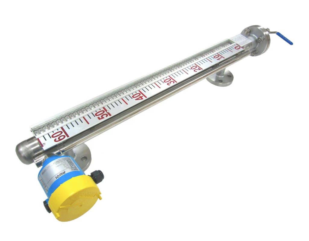
3. Reference Accuracy Is Not the Same as Installed Accuracy
A common mistake when selecting a remote transmitter is to compare two basic accuracy values, such as ±0.075% and ±0.1%, and assume that the transmitter with the smaller number will always provide better field performance.
In practice, the total accuracy of a remote measurement system depends on several sources of error.
The installed or total performance error may include:
- Transmitter reference accuracy;
- Remote diaphragm seal error;
- Ambient temperature effects;
- Process temperature effects;
- Static pressure effects;
- Mounting position effects;
- Capillary temperature difference;
- Long-term stability;
- Zero and span configuration error;
- Calibration error;
- Maintenance-related error.
Depending on the project standard, manufacturer, and industry requirements, these individual error components may be evaluated by direct addition, worst-case analysis, or a root-sum-square calculation.
The applicable method should be confirmed using the manufacturer’s technical documentation and the project’s instrument specification.
A transmitter with excellent sensor accuracy may still deliver poor field performance if it is combined with undersized diaphragm seals, unsuitable filling fluid, or unnecessarily long capillary tubes.
Conversely, a transmitter with slightly lower reference accuracy may perform better in practice if the complete remote seal system has been properly engineered for the application.
4. Major Factors Affecting Remote Transmitter Accuracy
4.1 Diaphragm Size
The remote diaphragm is one of the most important components in the pressure transmission system.
In general, a larger diaphragm can transfer pressure with less displacement per unit of applied pressure. Larger diaphragms often provide better sensitivity and improved temperature performance, particularly in low-pressure and small-span applications.
A small diaphragm has advantages such as compact size and easier installation. However, its greater mechanical stiffness may introduce more significant measurement effects.
The influence of diaphragm stiffness becomes especially important when measuring:
- Low pressure;
- Low differential pressure;
- Low liquid level;
- Low-density fluids;
- Vacuum conditions.
Therefore, engineers should not evaluate a small-span remote seal application solely on the basis of transmitter sensor performance. The size and design of the remote diaphragm must also be considered.
4.2 Capillary Length
A capillary tube connects the remote diaphragm seal to the transmitter body. It is filled with a pressure-transmitting fluid.
As capillary length increases, the total volume of filling fluid normally increases as well. A larger filling-fluid volume may produce greater expansion or contraction when temperature changes occur.
Excessively long capillary tubes can result in:
- Greater temperature-induced error;
- Slower response time;
- Increased sensitivity to temperature differences;
- More difficult installation and protection;
- Greater risk of mechanical damage;
- Higher maintenance requirements.
The capillary should therefore be long enough to meet installation, accessibility, and safety requirements, but it should not be made longer without a valid engineering reason.
Selecting an unnecessarily long capillary does not improve measurement quality. In many applications, it reduces system performance.
4.3 Filling Fluid Selection
The inside of the remote seal and capillary system is filled with a pressure-transmitting fluid.
Common filling fluids include:
- Standard silicone oil;
- High-temperature silicone oil;
- Low-temperature filling fluid;
- Inert filling fluid;
- Food-grade or sanitary filling fluid;
- Special fluids for vacuum service.
Different filling fluids have different:
- Thermal expansion coefficients;
- Viscosity characteristics;
- Operating temperature ranges;
- Vapor pressure characteristics;
- Vacuum resistance;
- Chemical and safety properties.
An unsuitable filling fluid may cause several problems.
At high temperatures, excessive fluid expansion may increase zero shift and measurement error. At low temperatures, increased viscosity may slow pressure transmission and extend response time.
Under vacuum conditions, an unsuitable filling fluid may vaporize or form gas pockets. In food and pharmaceutical applications, the filling fluid may also need to meet specific hygiene or safety requirements.
Filling-fluid selection should therefore consider:
- Minimum ambient temperature;
- Maximum ambient temperature;
- Minimum process temperature;
- Maximum process temperature;
- Process pressure;
- Vacuum conditions;
- Hygiene requirements;
- Chemical compatibility;
- Process safety requirements.
4.4 Ambient and Process Temperature
Temperature is one of the most common sources of error in remote seal transmitter installations.
Ambient temperature changes can affect the electronic components inside the transmitter. More importantly, they can cause the filling fluid inside the capillary to expand or contract.
Process temperature directly affects the remote diaphragm and can transfer heat into the filling system.
In a dual remote seal differential pressure transmitter used for vessel level measurement, unequal temperatures between the high-pressure and low-pressure capillaries may cause the filling fluids to expand by different amounts. This creates a differential pressure that does not come from the actual process level.
The result is often observed as zero drift.
To reduce this effect, the two capillaries should normally be:
- Equal in length;
- Identical in specification;
- Filled with the same fluid;
- Routed close together;
- Exposed to similar ambient conditions;
- Protected with equivalent insulation or shielding.
One capillary should not be exposed to direct sunlight while the other remains in shade. Similar problems can occur when one side is close to a hot pipe or heater and the other side is exposed to cold air.
4.5 Measuring Span and Turndown Ratio
Transmitter accuracy is frequently expressed as a percentage of the calibrated span.
When a transmitter is configured for a very small span, the same absolute sensor error represents a larger percentage of the measured value.
For example, a transmitter sensor may be capable of measuring a relatively large maximum range. However, if the configured field span uses only a very small part of that range, its total accuracy and stability may be affected by the turndown ratio.
This issue is especially important in:
- Low-level measurements;
- Low-density liquid applications;
- Small differential pressure measurements;
- Large vessels with a relatively small effective differential pressure;
- Applications requiring high turndown.
The transmitter sensor range should be selected according to the actual differential pressure generated by the process. Using an oversized sensor for a very small signal should be avoided whenever possible.
4.6 Installation Elevation
The filling fluid inside a remote seal system creates hydrostatic pressure.
When there is a height difference between the transmitter body and the remote diaphragm, the filling-fluid column produces a zero offset.
In a single remote seal pressure or level measurement, this effect usually appears as a fixed zero shift.
In a dual remote seal differential pressure level measurement, engineers must consider:
- The elevation difference between the upper and lower process connections;
- The transmitter mounting elevation;
- Filling-fluid density;
- Process-fluid density;
- Capillary arrangement;
- Vessel geometry.
A fixed zero offset can often be compensated for through zero elevation, zero suppression, or transmitter ranging.
However, compensation is reliable only when the installation geometry remains stable and the required zero shift remains within the transmitter’s allowable adjustment limits.
4.7 Static Pressure Effects
A differential pressure transmitter measures the difference between its high-pressure and low-pressure sides. However, both sides may also be exposed to high common-mode or static pressure.
For example, when a remote differential pressure transmitter measures level in a high-pressure closed vessel, the actual differential pressure may be only a few tens of kilopascals, while both sides are subjected to several megapascals of static pressure.
High static pressure may cause:
- Zero shift;
- Span shift;
- Sensor deformation;
- Reduced measurement stability.
For high-pressure applications, engineers should review the manufacturer’s static pressure effect specification rather than relying only on the reference accuracy stated under atmospheric or standard test conditions.
The transmitter’s maximum working pressure and overpressure rating must also be checked.
4.8 Response Time
Accuracy and response time are related to measurement performance, but they describe different characteristics.
Accuracy indicates how close the measured value is to the true value. Response time indicates how quickly the transmitter reacts to a process change.
The response time of a remote seal transmitter may be affected by:
- Capillary length;
- Capillary internal diameter;
- Filling-fluid viscosity;
- Ambient temperature;
- Process temperature;
- Diaphragm size;
- Sensor displacement.
Long capillaries and high-viscosity filling fluids generally increase response time. Low ambient temperatures may further increase filling-fluid viscosity and slow down pressure transmission.
For slowly changing storage tank level measurements, a longer response time may be acceptable.
For fast pressure control, shutdown systems, interlocks, or pulsating pressure monitoring, the dynamic response of the complete remote seal system should be carefully evaluated.
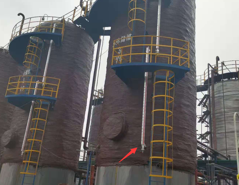
5. How to Calculate Remote Seal Transmitter Error
For a basic estimate, the permissible reference error can be calculated using the following formula:
Permissible basic error = Calibrated span × Accuracy rating
For example, consider a remote differential pressure transmitter configured for a range of 0 to 100 kPa with a stated reference accuracy of ±0.1% of span.
The calculated reference error is:
100 kPa × 0.1% = ±0.1 kPa
Suppose the transmitter is used to measure a liquid level range of 0 to 10 meters.
If process-fluid density variation, installation effects, and temperature effects are temporarily ignored, the corresponding basic level error would be approximately ±0.1% of the full level range.
This is equivalent to approximately:
10 m × 0.1% = ±0.01 m
Therefore, the theoretical basic level error would be about ±10 mm.
However, a practical calculation should also include other error sources, such as:
- Ambient temperature effects;
- Process temperature effects;
- Static pressure effects;
- Remote seal temperature effects;
- Capillary effects;
- Long-term drift;
- Calibration uncertainty.
For dual remote level measurement, changes in process-fluid density can also create significant level conversion errors.
A differential pressure transmitter measures pressure difference rather than physical liquid height directly. If the actual process density differs from the density used during transmitter configuration, the calculated level may be incorrect even when the differential pressure measurement itself is accurate.
6. How to Improve Remote Seal Transmitter Accuracy
6.1 Select an Appropriate Measuring Range
The measuring range should be selected according to:
- Normal operating pressure or level;
- Minimum operating value;
- Maximum operating value;
- Startup and shutdown conditions;
- Abnormal operating conditions;
- Required measurement resolution.
The normal operating point should ideally remain within an effective part of the calibrated span.
The transmitter should not operate continuously near zero, and the measurement should not frequently exceed the configured upper range limit.
6.2 Minimize Capillary Length
Within the limits of installation access, safety, and maintenance requirements, capillary length should be kept as short as reasonably possible.
A shorter capillary reduces filling-fluid volume and can improve:
- Temperature performance;
- Response time;
- Mechanical reliability;
- Installation simplicity.
However, the transmitter should not be mounted in an unsuitable location merely to shorten the capillary.
A short capillary does not compensate for severe vibration, excessive heat, poor accessibility, or an unsafe mounting position.
6.3 Keep Both Sides Symmetrical
For a dual remote seal differential pressure transmitter, both capillary systems should normally have:
- The same length;
- The same diameter;
- The same construction;
- The same filling fluid;
- Similar routing;
- Similar insulation;
- Similar exposure to sunlight and heat sources.
Symmetrical installation helps reduce differential temperature effects.
The two capillaries should preferably be routed together wherever practical. If tracing or insulation is required, it should be applied consistently to both sides.
6.4 Configure Zero Elevation or Suppression Correctly
After installation, the zero point should be checked based on:
- Actual process connection elevations;
- Transmitter mounting position;
- Capillary arrangement;
- Filling-fluid density;
- Process-fluid density.
When zero elevation or zero suppression is required, the calculated offset must remain within the transmitter’s allowable lower and upper range limits.
Improper zero migration can reduce usable span or cause the transmitter to reach its measurement limit before the process reaches its intended operating range.
6.5 Protect the System from Temperature Extremes
For outdoor installations, suitable protection may include:
- Sunshades;
- Thermal insulation;
- Weatherproof instrument enclosures;
- Consistent capillary routing;
- Protection from hot surfaces;
- Protection from cold drafts.
The transmitter and capillary should be kept away from intense localized heat radiation whenever possible.
If the capillary passes near high-temperature piping, sufficient spacing and thermal protection should be provided.
6.6 Perform Periodic Calibration and Inspection
Remote transmitters should be calibrated according to the facility’s maintenance and metrology procedures.
Inspection should cover more than the transmitter’s electrical output.
The maintenance team should also check whether:
- The remote diaphragm is deformed;
- The diaphragm is corroded;
- Deposits have formed on the diaphragm;
- The capillary is bent or crushed;
- Filling fluid has leaked;
- Flange connections are loose;
- Seals or gaskets are damaged;
- The transmitter mounting position has changed.
A transmitter cannot maintain reliable accuracy if the diaphragm or filling system has been physically damaged.
7. Which Accuracy Specifications Should Be Reviewed?
When selecting a remote pressure transmitter or remote differential pressure transmitter, engineers should review more than the basic accuracy specification.
Important parameters include:
- Reference accuracy;
- Linearity;
- Hysteresis;
- Repeatability;
- Ambient temperature effect;
- Process temperature effect;
- Static pressure effect;
- Turndown-related error;
- Long-term stability;
- Remote seal additional error;
- Capillary length;
- Response time;
- Filling-fluid operating temperature range;
- Zero elevation and suppression capability;
- Overpressure rating;
- Maximum static pressure;
- Diaphragm material;
- Flange material;
- Corrosion resistance;
- Vacuum suitability.
Accuracy definitions may differ between manufacturers.
When comparing products, determine whether the stated accuracy is expressed as a percentage of:
- Calibrated span;
- Upper range limit;
- Full scale;
- Measured reading.
It is also important to determine whether the stated accuracy includes linearity, hysteresis, and repeatability, or whether these values are specified separately.
A small accuracy number is meaningful only when its test conditions and calculation basis are clearly understood.
8. Is Higher Remote Transmitter Accuracy Always Better?
From a measurement perspective, higher accuracy is generally beneficial. However, not every application requires the highest available accuracy class.
If the process can tolerate a relatively large measurement uncertainty, selecting an extremely high-accuracy transmitter may increase:
- Purchase cost;
- Calibration cost;
- Maintenance requirements;
- Engineering complexity;
- Spare-parts cost.
Higher accuracy may be particularly important in applications involving:
- Custody transfer or commercial measurement;
- Critical chemical reaction control;
- Safety interlocks;
- High-value process materials;
- Small-span differential pressure measurement;
- Low-density fluid level measurement;
- High static pressure with low differential pressure;
- Strict product quality control.
For general process monitoring, the transmitter should provide sufficient accuracy to meet the actual process requirement.
The best transmitter is not necessarily the model with the smallest percentage printed on the datasheet. It is the transmitter whose complete measurement system is correctly matched to the process conditions.
In many remote seal applications, diaphragm size, capillary length, filling-fluid selection, temperature exposure, installation quality, and maintenance practices have a greater influence on field performance than a small improvement in transmitter sensor accuracy.
9. Frequently Asked Questions
9.1 Which Is More Accurate: a Remote Seal Transmitter or a Conventional Transmitter?
When the same sensing technology and calibrated span are used, a conventional direct-mounted transmitter normally has a shorter measurement chain and fewer additional sources of error.
A remote seal transmitter is mainly selected because it can handle difficult process conditions, such as high temperature, corrosion, viscosity, crystallization, and clogging.
It should not automatically be assumed to provide greater accuracy than a conventional transmitter.
9.2 Does a Shorter Capillary Always Improve Accuracy?
A shorter capillary generally helps reduce temperature effects and improve response time.
However, the capillary must still be long enough to allow safe installation, suitable transmitter placement, and convenient maintenance.
The transmitter should not be installed in a high-temperature, high-vibration, inaccessible, or unsafe location solely to minimize capillary length.
9.3 Why Does a Dual Remote Seal Transmitter Experience Zero Drift?
Common causes include:
- Unequal capillary temperatures;
- Thermal expansion or contraction of filling fluid;
- Changes in installation elevation;
- Uneven diaphragm temperature;
- Deposits on the diaphragm;
- Transmitter temperature drift;
- Damage to a capillary;
- Filling-fluid leakage.
When zero drift varies with the time of day or weather conditions, unequal solar heating of the two capillaries should be investigated.
9.4 Can a Remote Transmitter Be Zeroed in the Field?
Most smart pressure and differential pressure transmitters support field zero adjustment.
However, zero adjustment only compensates for a fixed offset under the current installation conditions.
It cannot eliminate dynamic errors caused by:
- Changing temperature;
- Damaged diaphragms;
- Filling-fluid leakage;
- Unstable process density;
- Unequal capillary heating;
- Mechanical deformation.
Repeatedly adjusting the zero without identifying the underlying cause may hide a developing instrument problem.
9.5 What Is Most Commonly Overlooked When Evaluating Accuracy?
The most commonly overlooked issue is the additional error introduced by the remote seal system.
Users often focus only on transmitter sensor accuracy while ignoring:
- Diaphragm size;
- Capillary length;
- Filling-fluid properties;
- Ambient temperature differences;
- Process temperature;
- Static pressure;
- Installation elevation.
A reliable accuracy evaluation must consider the complete installed system rather than the transmitter body alone.
10. Conclusion
Remote transmitter accuracy is not determined by a single specification.
It is the result of the combined performance of:
- The transmitter sensor;
- The remote diaphragm seal;
- The capillary system;
- The filling fluid;
- The installation arrangement;
- The process conditions;
- The surrounding environment.
Before selecting a remote transmitter, engineers should clearly define:
- Measurement range;
- Process temperature;
- Ambient temperature;
- Process-fluid characteristics;
- Installation elevation;
- Static pressure;
- Required response time;
- Allowable measurement error.
Based on these conditions, an appropriate transmitter sensor range, diaphragm size, capillary length, filling fluid, and installation method can be selected.
For general process monitoring, the transmitter only needs to satisfy the actual control and indication requirements.
For low-span level measurement, high-static-pressure differential pressure measurement, or installations with large temperature differences, a complete system accuracy analysis should be performed.
Only by considering the product specifications, process requirements, installation conditions, and maintenance practices together can users achieve reliable remote seal transmitter accuracy, long-term stability, and dependable measurement performance.

