
Intrinsically safe level instruments are widely used in hazardous areas containing flammable gases, vapors, or combustible dust. Typical applications include oil tanks, chemical reactors, storage vessels, silos, pharmaceutical plants, gas facilities, and process pipelines.
A common question is:
If a level instrument is already certified as intrinsically safe, why does it still need a safety barrier?
The answer is that intrinsic safety applies to the complete electrical circuit, not only to the field instrument.
An intrinsically safe level instrument is designed to operate safely within specified limits for voltage, current, power, capacitance, and inductance. A safety barrier limits the energy entering the hazardous area and prevents faults in the control system from sending dangerous levels of electrical energy to the field device.
The level instrument, safety barrier, cable, and control system must therefore be evaluated as one complete intrinsically safe loop.
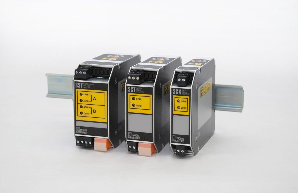
Frequently Asked Questions About Intrinsically Safe Level Instruments and Safety Barriers
1. What is an intrinsically safe level instrument?
An intrinsically safe level instrument is a level measurement device designed so that its electrical circuits cannot release enough electrical or thermal energy to ignite a surrounding explosive atmosphere under specified operating and fault conditions.
Instead of containing an explosion inside a heavy enclosure, intrinsic safety prevents ignition by limiting electrical energy.
Common intrinsically safe level instruments include:
- Radar level transmitters
- Ultrasonic level transmitters
- Hydrostatic level transmitters
- Submersible level transmitters
- Magnetostrictive level transmitters
- RF admittance level instruments
- Capacitance level transmitters
- Level switches
- Interface level transmitters
These instruments are commonly installed in hazardous areas and connected to PLC, DCS, remote I/O, or monitoring systems located in a safe area.
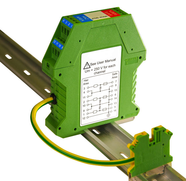
2. Why does an intrinsically safe level instrument need a safety barrier?
An intrinsically safe level instrument needs a safety barrier because the instrument alone cannot control the amount of electrical energy supplied by the external circuit.
The safety barrier limits the voltage, current, and power that can enter the hazardous area.
Without a certified safety barrier or other approved associated apparatus, a fault in the power supply, PLC, DCS, or field wiring could send excessive energy to the level instrument.
This means that a certified intrinsically safe level transmitter cannot automatically be connected directly to an ordinary 24 VDC power supply or standard analog input module.
3. What is the main function of a safety barrier?
The main function of a safety barrier is to prevent excessive electrical energy from entering a hazardous area.
A safety barrier typically performs one or more of the following functions:
- Limits maximum voltage
- Limits maximum current
- Limits maximum output power
- Transfers the measurement signal
- Supplies power to a two-wire field transmitter
- Provides galvanic isolation
- Reduces ground-loop interference
- Protects the hazardous-area circuit from safe-area faults
In a level measurement loop, the barrier forms the energy-control boundary between the field instrument and the control system.
4. Is a safety barrier the same as a fuse?
No. A safety barrier is not the same as a fuse.
A fuse primarily protects equipment and wiring against excessive current. It does not necessarily limit voltage, stored energy, capacitance, inductance, or fault power to the levels required for an intrinsically safe circuit.
A certified intrinsic safety barrier is specifically designed and evaluated to control the maximum energy that can reach the hazardous area.
Although some Zener barriers contain a fuse as part of their protection circuit, the fuse alone does not provide intrinsic safety.
5. Is a safety barrier the same as a surge protector?
No. A safety barrier and a surge protective device have different purposes.
A safety barrier limits electrical energy entering a hazardous area under normal and specified fault conditions.
A surge protector is designed mainly to reduce temporary overvoltage caused by lightning, switching operations, or electromagnetic disturbances.
In outdoor tank farms, long cable installations, or lightning-prone locations, a system may require both:
- An intrinsic safety barrier
- A suitable surge protective device
One device should not automatically be used as a substitute for the other.
6. Can an intrinsically safe level transmitter be connected directly to 24 VDC?
Normally, no.
An ordinary 24 VDC power supply is not automatically an intrinsically safe power source. Even if its normal output voltage appears suitable, it may be capable of supplying excessive current or power under fault conditions.
A two-wire intrinsically safe level transmitter should normally be connected through one of the following:
- A certified galvanically isolated safety barrier
- A certified Zener barrier
- An intrinsically safe repeater power supply
- A certified intrinsically safe I/O channel
- Another approved item of associated apparatus
The complete circuit must satisfy the relevant intrinsic safety parameter requirements.
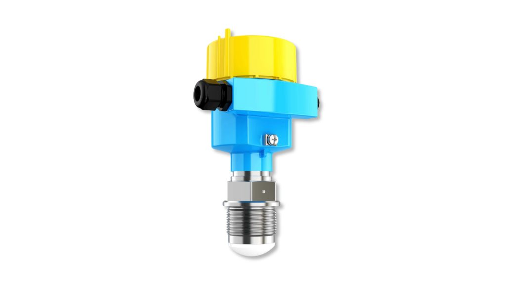
7. Does every intrinsically safe level instrument need a separate barrier module?
Not always.
Every intrinsically safe field circuit requires suitable certified energy-limiting equipment, but this equipment does not always have to be a separate DIN-rail safety barrier.
A separate barrier may not be required when the level instrument is connected to:
- A PLC input module with certified intrinsically safe channels
- A DCS card with integrated intrinsic safety protection
- A certified intrinsically safe remote I/O module
- An approved intrinsically safe power supply
- A certified signal converter with integrated energy limitation
In these cases, the energy-limiting function is already built into the control or interface equipment.
However, the output parameters of the integrated module must still be checked against the input parameters of the level instrument.
8. What is associated apparatus in an intrinsically safe system?
Associated apparatus is equipment that connects to an intrinsically safe circuit and limits or controls the energy supplied to the hazardous area.
A safety barrier is a common example of associated apparatus.
Associated apparatus is usually installed in a safe area, although some certified products may be installed in specific hazardous locations according to their approval.
Examples include:
- Galvanic isolators
- Zener barriers
- Intrinsically safe repeater power supplies
- Intrinsically safe I/O modules
- Certified signal conditioners
- Intrinsically safe power supplies
The associated apparatus is essential because it prevents faults on the non-intrinsically safe side from creating an ignition risk in the hazardous area.
9. What is the difference between a Zener barrier and a galvanically isolated barrier?
A Zener barrier limits energy using components such as current-limiting resistors, Zener diodes, and fuse protection.
A galvanically isolated barrier uses electrical isolation technologies such as transformers or optocouplers to separate the field circuit from the control circuit.
Zener Barrier
A Zener barrier is generally:
- Economical
- Compact
- Simple in design
- Dependent on a reliable intrinsic safety earth
- More sensitive to grounding quality
- More likely to introduce loop voltage drop
Galvanically Isolated Barrier
A galvanically isolated safety barrier generally provides:
- Electrical isolation between input and output
- Reduced risk of ground loops
- Better resistance to common-mode interference
- Easier integration into complex control systems
- Less dependence on a Zener-style intrinsic safety earth
- Improved performance for long cable runs
Galvanically isolated barriers are often preferred for modern PLC and DCS installations, especially where grounding conditions or electrical noise are a concern.
10. Which safety barrier is better for a level transmitter?
The best safety barrier depends on the instrument signal, power requirement, communication protocol, grounding system, cable length, and control system interface.
A galvanically isolated barrier is often preferred when:
- The cable distance is long
- HART communication is required
- Ground-loop problems are possible
- Electrical interference is significant
- Different grounding systems are involved
- The installation uses PLC or DCS analog inputs
- Simplified commissioning is important
A Zener barrier may be suitable when:
- A compliant intrinsic safety earth is available
- The loop voltage calculation allows the additional voltage drop
- The project requires a lower-cost solution
- The system design is relatively simple
The final selection should always be based on certificate data and electrical compatibility.
11. How does a safety barrier work with a two-wire 4–20 mA level transmitter?
A two-wire 4–20 mA level transmitter uses the same two conductors for power and signal transmission.
The safety barrier supplies limited electrical power to the transmitter while allowing the 4–20 mA measurement signal to pass back to the PLC or DCS.
The barrier must provide enough voltage for:
- The level transmitter
- Cable resistance
- The control system input load
- Internal barrier voltage drop
- Any additional loop resistance
If the available loop voltage is too low, the transmitter may fail to start or may be unable to reach its full 20 mA output.
12. What happens if the safety barrier does not provide enough voltage?
If the safety barrier does not provide sufficient operating voltage, the level transmitter may experience several problems.
Possible symptoms include:
- Failure to power up
- Repeated restarts
- Unstable output
- Incorrect level readings
- Inability to reach 20 mA
- Signal loss at high process values
- HART communication failure
- Fault output during startup
- Intermittent operation
A proper loop voltage calculation should be completed before selecting the barrier.
The calculation should consider the power supply voltage, barrier voltage drop, minimum transmitter operating voltage, cable resistance, input resistance of the PLC or DCS, and a suitable engineering margin.
13. Can a standard signal isolator replace an intrinsically safe barrier?
No, unless the signal isolator is specifically certified as associated apparatus for intrinsic safety.
A standard signal isolator may provide electrical separation, but it may not limit voltage, current, and power to safe values under fault conditions.
The product documentation should clearly identify the device as suitable for connection to intrinsically safe circuits.
An ordinary isolator should not be used merely because it has similar terminals or signal specifications.
14. How do you match a level instrument with a safety barrier?
A level instrument and safety barrier must be matched using their certified intrinsic safety parameters.
The safety barrier normally has output parameters including:
- Uo: maximum output voltage
- Io: maximum output current
- Po: maximum output power
- Co: maximum permitted external capacitance
- Lo: maximum permitted external inductance
The level instrument normally has input parameters including:
- Ui: maximum permitted input voltage
- Ii: maximum permitted input current
- Pi: maximum permitted input power
- Ci: internal capacitance
- Li: internal inductance
The following relationships normally need to be satisfied:
Uo ≤ Ui
Io ≤ Ii
Po ≤ Pi
Ci + Ccable ≤ Co
Li + Lcable ≤ Lo
These values must be taken from the relevant certificates, control drawings, and manufacturer documentation.
15. Why must cable capacitance and inductance be included?
A field cable stores electrical energy through its capacitance and inductance.
Even when the safety barrier and level instrument are individually compatible, a long cable can add enough capacitance or inductance to exceed the permitted limits of the intrinsically safe circuit.
The calculation should include:
- Internal capacitance of the level instrument
- Internal inductance of the level instrument
- Total cable capacitance
- Total cable inductance
- Maximum permitted external capacitance of the barrier
- Maximum permitted external inductance of the barrier
Cable parameters become especially important in long-distance installations such as tank farms, pipeline terminals, large chemical plants, and remote storage facilities.
16. Can two certified devices always be connected together?
No.
Two devices with valid explosion-protection certificates are not automatically compatible.
The safety barrier may have output parameters that exceed the permitted input parameters of the level instrument.
The cable may also cause the combined capacitance or inductance to exceed the permitted limits.
In addition, the two devices may have incompatible:
- Gas groups
- Equipment protection levels
- Temperature classifications
- Signal directions
- Power requirements
- Communication protocols
- Environmental ratings
- Special conditions of use
The complete loop must be evaluated before installation.
17. Does a HART radar level transmitter need a special safety barrier?
A HART-enabled radar level transmitter should be used with a safety barrier that supports HART communication.
HART communication uses a digital signal superimposed on the 4–20 mA analog signal. A barrier that does not provide suitable frequency response or signal transparency may block or weaken the HART signal.
When selecting a safety barrier for a HART radar level transmitter, verify:
- HART compatibility
- Two-wire transmitter power capability
- Available loop voltage
- Output load range
- Intrinsic safety parameters
- Communication access points
- PLC or DCS input compatibility
A barrier may pass the 4–20 mA current correctly while still preventing reliable HART communication.
18. Where should the safety barrier be installed?
A safety barrier is normally installed in the safe-area control cabinet.
The hazardous-area side of the barrier is connected to the field level instrument. The safe-area side is connected to the PLC, DCS, power supply, display, or signal-processing equipment.
The intrinsically safe and non-intrinsically safe terminals must be clearly identified.
The barrier should be installed according to:
- Manufacturer instructions
- Certificate requirements
- Applicable electrical codes
- Cabinet spacing requirements
- Grounding requirements
- Environmental limits
- Temperature limits
Incorrect terminal connections may damage the device or invalidate the intrinsic safety protection.
19. Can intrinsically safe and non-intrinsically safe cables be installed together?
They should normally be separated or installed according to the applicable intrinsic safety wiring requirements.
Intrinsically safe circuits must be protected from accidental contact with higher-energy non-intrinsically safe circuits.
Separation may be achieved through:
- Separate cable trays
- Separate wiring ducts
- Physical spacing
- Approved partitions
- Suitable insulation
- Clearly identified terminals
- Proper cable marking
The exact installation method should follow the relevant standards, project specifications, and local regulations.
20. Does the cable shield need to be grounded?
The cable shield should be grounded according to the overall system design and the equipment manufacturer’s instructions.
In many analog measurement systems, the shield is grounded at one end to reduce the risk of ground-loop current.
However, the correct method depends on:
- Barrier type
- Control system grounding
- Field enclosure grounding
- Cable length
- Electromagnetic interference
- Surge protection arrangement
- Equipotential bonding
The shield should not be grounded at both ends without evaluating the possibility of ground loops and circulating currents.
21. Can the safety barrier be bypassed during commissioning?
A safety barrier should not be bypassed when the field circuit is located in a hazardous area.
Bypassing the barrier removes the certified energy limitation and may allow dangerous electrical energy to enter the field circuit.
Commissioning and troubleshooting should be performed using approved procedures, suitable test equipment, and the manufacturer’s instructions.
The fact that a temporary direct connection appears to work electrically does not make it safe or compliant.
22. What can happen if the wrong safety barrier is selected?
Selecting the wrong safety barrier may cause both safety and operational problems.
Possible consequences include:
- Loss of intrinsic safety compliance
- Excessive energy entering the hazardous area
- Failure of the level transmitter to start
- Incorrect 4–20 mA signal
- Reduced measurement accuracy
- HART communication failure
- Excessive loop voltage drop
- Unstable readings
- PLC or DCS input mismatch
- Failed inspection or certification
- Increased ignition risk
Barrier selection should therefore be treated as part of the instrument loop design, not as a simple accessory purchase.
23. Is a higher-rated safety barrier always better?
No.
A safety barrier with a higher output voltage, current, or power may exceed the input limits of the level instrument.
For intrinsic safety, higher output capacity does not necessarily mean better performance or greater safety.
The correct barrier is one whose output parameters are compatible with the field instrument while still providing enough normal operating energy for reliable measurement.
24. Can multiple safety barriers be connected in series?
Multiple barriers should not be connected in series unless the complete arrangement has been specifically designed and evaluated.
Installing extra barriers does not automatically improve protection.
Series-connected barriers may create:
- Excessive voltage drop
- Signal distortion
- Incorrect current readings
- HART communication problems
- Power supply failure
- Unstable transmitter operation
A single correctly selected and certified interface is normally the preferred solution.
25. What information is required when selecting a safety barrier?
The following information should be collected before selecting a safety barrier:
- Level instrument model
- Explosion-protection marking
- Intrinsic safety input parameters
- Signal type
- Two-wire or four-wire configuration
- Active or passive output
- HART communication requirement
- Power supply voltage
- Minimum operating voltage
- Cable length
- Cable resistance
- Cable capacitance
- Cable inductance
- PLC or DCS input type
- Input resistance
- Hazardous-area classification
- Gas or dust group
- Temperature class
- Ambient temperature range
- Grounding conditions
Providing complete loop information helps prevent incorrect barrier selection.
26. Which level instruments commonly require safety barriers?
Safety barriers are commonly used with intrinsically safe versions of:
- Radar level transmitters
- Guided wave radar level transmitters
- Ultrasonic level transmitters
- Hydrostatic level transmitters
- Submersible pressure level transmitters
- Magnetostrictive level transmitters
- Capacitance level transmitters
- Differential pressure level transmitters
- RF admittance level instruments
- Float level switches
- Conductivity level switches
- NAMUR level switches
Whether a barrier is required depends on the complete system architecture and whether the control-side equipment already provides a certified intrinsically safe interface.
27. Are safety barriers required in dust hazardous areas?
Safety barriers may be required when an intrinsically safe level instrument is installed in an area containing combustible dust.
However, the equipment and system must be suitable for the specific dust environment.
The design should consider:
- Dust group
- Equipment protection level
- Maximum surface temperature
- Ambient temperature
- Dust layer accumulation
- Enclosure ingress protection
- Electrostatic charging
- Cable entry protection
- Applicable certificate conditions
A barrier approved for a gas application should not automatically be assumed suitable for every dust application.
28. What documents should be checked before installation?
The following documents should normally be reviewed:
- Level instrument datasheet
- Level instrument explosion-protection certificate
- Safety barrier datasheet
- Safety barrier certificate
- Control drawing
- Wiring diagram
- Installation manual
- Cable specification
- Intrinsic safety calculation
- Hazardous-area classification drawing
- Loop diagram
- Junction box schedule
- Grounding specification
- Inspection and commissioning procedure
Any special conditions identified in the certificates must be included in the installation design.
29. Does replacing a level transmitter require a new intrinsic safety check?
Yes, if the replacement model or certification data differs from the original device.
Even when the replacement transmitter uses the same 4–20 mA signal and supply voltage, its Ui, Ii, Pi, Ci, and Li values may be different.
The replacement may also have a different:
- Explosion-protection marking
- Gas group
- Temperature class
- Ambient temperature range
- Enclosure rating
- HART requirement
- Minimum operating voltage
The loop documentation should be reviewed and updated before the replacement device is placed into service.
30. What is the most important rule for intrinsically safe level instrument installation?
The most important rule is to treat the field instrument, safety barrier, cable, and control system as one complete electrical loop.
Intrinsic safety cannot be confirmed by checking only the level instrument certificate.
The complete system must satisfy the required electrical parameters, hazardous-area classification, environmental conditions, wiring rules, grounding requirements, and certificate conditions.
Quick Safety Barrier Selection Checklist
Before purchasing or installing a safety barrier, confirm the following:
- Is the level instrument certified as intrinsically safe?
- Is the barrier certified as suitable associated apparatus?
- Does the barrier support the correct signal type?
- Does it support HART communication when required?
- Are Uo, Io, and Po within the instrument’s Ui, Ii, and Pi limits?
- Are cable capacitance and inductance included in the calculation?
- Is sufficient loop voltage available?
- Is the PLC or DCS input compatible?
- Are the gas or dust group requirements satisfied?
- Are the temperature class and ambient limits acceptable?
- Have all special conditions of use been reviewed?
- Are intrinsically safe and non-intrinsically safe wiring properly separated?
- Has the completed loop been documented and verified?
Final Answer
An intrinsically safe level instrument needs a safety barrier because the instrument alone cannot prevent excessive energy from entering the hazardous area.
The safety barrier limits voltage, current, and power, protects the field circuit from control-system faults, and allows the measurement signal to be transmitted safely.
A separate barrier may not be necessary when a certified intrinsically safe I/O module or power supply already provides the required energy limitation.
However, the complete circuit must always be checked for parameter compatibility, including the level instrument, barrier, cable, control system, grounding arrangement, hazardous-area classification, and certificate conditions.
Correct safety barrier selection is essential not only for explosion protection, but also for stable 4–20 mA transmission, reliable HART communication, accurate level measurement, and long-term system performance.

