
Introduction
Transistors are among the most fundamental components in modern electronics. They are widely used in switching circuits, signal amplification, voltage regulation, power control, digital logic, and industrial automation systems.
Among the most common types of bipolar junction transistors, or BJTs, are NPN transistors and PNP transistors. Although both devices have three terminals and similar operating principles, their semiconductor structure, current direction, polarity, and typical applications are different.
Understanding the difference between PNP and NPN transistors is essential for circuit design, component selection, signal processing, and reliable electronic system development.
Basic Structure of a Transistor
A bipolar junction transistor consists of three semiconductor layers that form two PN junctions. It has three terminals:
Emitter: Supplies charge carriers into the transistor.
Base: A thin control region that regulates current flow between the emitter and collector.
Collector: Collects the charge carriers and delivers output current to the external circuit.
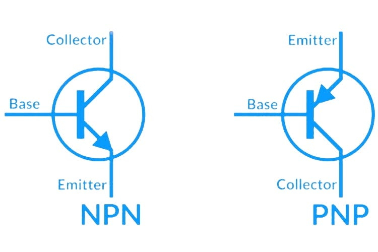
The arrangement of P-type and N-type semiconductor materials determines whether the device is an NPN transistor or a PNP transistor.
What Is an NPN Transistor?
An NPN transistor is made of two N-type semiconductor layers separated by a thin P-type base region. It is one of the most widely used transistor types because electrons, the main charge carriers in NPN devices, have high mobility.
Structure of an NPN Transistor
An NPN transistor includes:
Emitter: N-type semiconductor that injects electrons.
Base: Thin P-type semiconductor region used to control current.
Collector: N-type semiconductor that collects electrons flowing through the base.
Working Principle of an NPN Transistor
In an NPN transistor, a small positive current applied to the base allows a larger current to flow from the collector to the emitter in the conventional current direction.
When the base-emitter junction is forward biased, electrons move from the emitter into the base. Because the base region is very thin, most electrons pass through it and are collected by the collector. This produces a larger collector current.
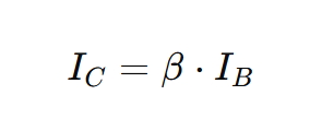
The current gain relationship is commonly expressed as:
Where:
IC = collector current
IB = base current
β = DC current gain of the transistor
Key Features of NPN Transistors
NPN transistors are commonly used because they offer fast switching speed, high efficiency, and strong performance in digital and high-frequency circuits. They are often preferred in low-side switching circuits, microcontroller interfaces, signal amplifiers, and power control applications.
What Is a PNP Transistor?
A PNP transistor has two P-type semiconductor layers separated by a thin N-type base region. Unlike an NPN transistor, a PNP transistor uses holes as the main charge carriers.
Structure of a PNP Transistor
A PNP transistor includes:
Emitter: P-type semiconductor that injects holes.
Base: Thin N-type semiconductor region that controls current flow.
Collector: P-type semiconductor that collects holes passing through the base.
Working Principle of a PNP Transistor
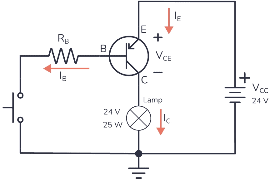
A PNP transistor turns on when the base voltage is lower than the emitter voltage. In this condition, current can flow from the emitter to the collector in the conventional current direction.
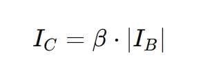
The base current flows out of the base terminal, which is the opposite of an NPN transistor. Because of this reversed polarity, PNP transistors are often used in high-side switching circuits and complementary amplifier designs.
Key Features of PNP Transistors
PNP transistors are useful in circuits where the load needs to be connected to the positive supply side. They are also commonly paired with NPN transistors in push-pull amplifier circuits, power regulation circuits, and complementary switching designs.
PNP vs NPN Transistors: Key Differences
| Feature | NPN Transistor | PNP Transistor |
|---|---|---|
| Semiconductor Structure | N-P-N | P-N-P |
| Main Charge Carrier | Electrons | Holes |
| Base Control | Turns on when base is positive relative to emitter | Turns on when base is negative relative to emitter |
| Conventional Current Direction | Collector to emitter | Emitter to collector |
| Common Switching Use | Low-side switching | High-side switching |
| Typical Applications | Digital circuits, high-speed switching, power control | Complementary circuits, analog circuits, high-side switching |
| Common Usage | More widely used | Used where polarity or circuit design requires it |
Although PNP and NPN transistors perform similar functions, they are not interchangeable without changing the circuit polarity and biasing method.
Common Applications of PNP and NPN Transistors
1. Switching Circuits
Transistors are often used as electronic switches.
An NPN transistor is commonly used as a low-side switch, where the load is connected between the positive supply and the collector. When base current is applied, the transistor turns on and completes the path to ground.
A PNP transistor is commonly used as a high-side switch, where the load is connected between the collector and ground. The transistor turns on when the base is pulled lower than the emitter.
2. Amplifier Circuits
Both NPN and PNP transistors can amplify signals. A small input signal at the base controls a larger current between the collector and emitter.
NPN transistors are often preferred in high-frequency amplification because of their faster electron mobility. PNP transistors are commonly used in complementary amplifier stages, especially when paired with NPN devices.
3. Digital Circuits
NPN transistors are widely used in digital logic circuits, microcontroller output stages, relay drivers, LED drivers, and transistor-transistor logic circuits.
PNP transistors may be used for level shifting, high-side control, or complementary logic arrangements.
4. Power Management
PNP and NPN transistors are also used in voltage regulation, current limiting, overload protection, and power switching circuits. By controlling current flow precisely, they help improve circuit stability and efficiency.
Practical Design Considerations
When choosing between a PNP and NPN transistor, engineers should consider the following factors:
Base Resistor Selection
A base resistor is necessary to limit base current and protect the transistor. The resistor value should be calculated according to the required base current and the desired operating mode, such as switching or amplification.
Power Dissipation
The transistor must operate within its rated power limits. Excessive collector-emitter voltage or collector current can cause overheating and device failure.
Temperature Effects
Temperature changes can affect transistor gain, leakage current, and operating point. Heat dissipation and proper thermal design are important in power circuits.
Switching Speed
NPN transistors are often preferred for high-speed switching because electron mobility is higher than hole mobility. For high-frequency designs, switching time and transistor capacitance should be carefully evaluated.
Complementary Design
NPN and PNP transistors are frequently used together in push-pull amplifiers and power output stages. This complementary configuration improves efficiency, linearity, and output performance.
Modern Examples of PNP and NPN Transistor Applications
Audio Amplifiers
Push-pull audio amplifier circuits often use complementary NPN and PNP transistor pairs. The NPN transistor handles one half of the waveform, while the PNP transistor handles the other half. This improves output efficiency and reduces distortion.
Microcontroller Interfaces
A microcontroller output pin usually cannot drive high-current loads directly. An NPN transistor can be used to control relays, LEDs, buzzers, motors, and other external loads with a small control signal.
Voltage Regulation
PNP transistors can be used in low-dropout linear regulator circuits, while NPN transistors are often used in switching regulators and current control circuits. Both types help maintain stable voltage and current output.
How to Choose Between PNP and NPN Transistors
Choose an NPN transistor when the circuit requires low-side switching, fast response, simple microcontroller control, or high-frequency operation.
Choose a PNP transistor when the circuit requires high-side switching, positive supply control, or complementary operation with an NPN transistor.
In many practical designs, both transistor types are used together to achieve better performance, higher efficiency, and more flexible circuit control.
Conclusion
PNP and NPN transistors are essential components in electronic circuit design. Their main differences lie in semiconductor structure, charge carriers, current direction, and biasing polarity.
NPN transistors are widely used in digital circuits, switching applications, and high-speed control systems. PNP transistors are commonly used in high-side switching, analog circuits, complementary amplifiers, and power management designs.
By understanding how PNP and NPN transistors work, engineers can select the right device for switching, amplification, voltage regulation, signal processing, and industrial control applications.
FAQ
What is the main difference between PNP and NPN transistors?
The main difference is the direction of current flow and the type of charge carrier. NPN transistors use electrons as the main carriers, while PNP transistors use holes. They also require opposite biasing polarities.
Which is more commonly used, PNP or NPN?
NPN transistors are more commonly used because they typically offer faster switching performance and are easier to drive in many digital and microcontroller circuits.
Can I replace a PNP transistor with an NPN transistor?
Not directly. PNP and NPN transistors have opposite polarity and current flow. Replacing one with the other usually requires changing the circuit design.
Where are NPN transistors used?
NPN transistors are commonly used in low-side switching, relay drivers, LED drivers, digital logic circuits, signal amplifiers, and microcontroller interfaces.
Where are PNP transistors used?
PNP transistors are commonly used in high-side switching, complementary amplifier circuits, voltage regulation, analog circuits, and power control applications.

