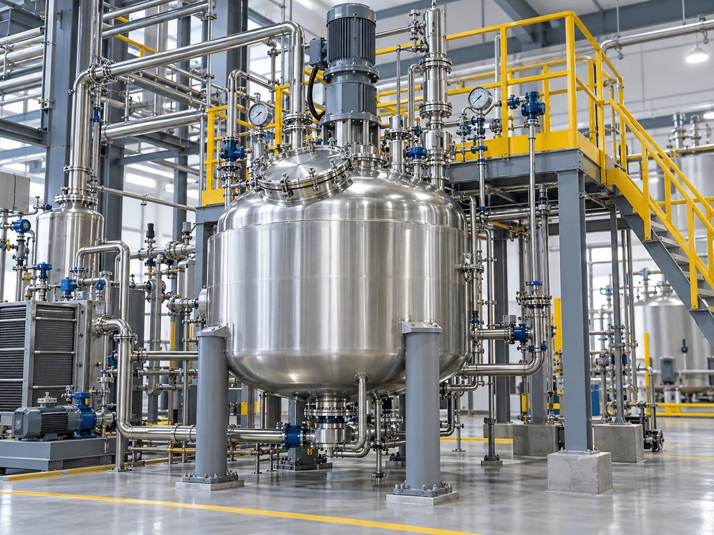
Resin production is a typical example of why reactor level measurement cannot be treated like ordinary storage tank measurement. Radar Level
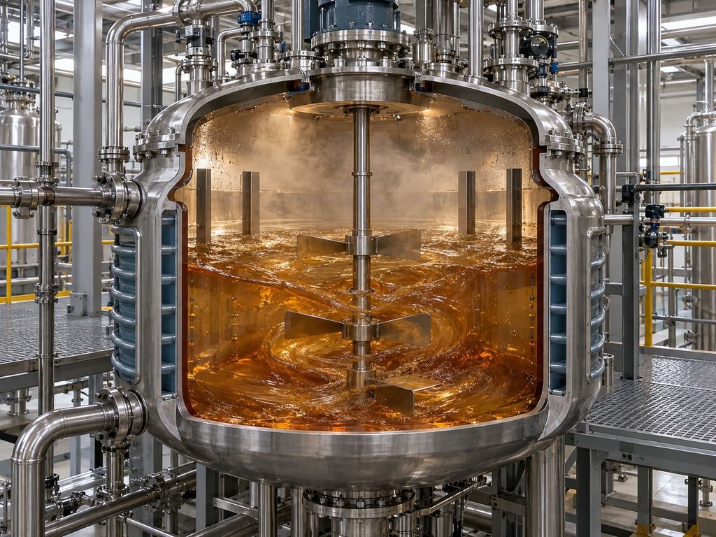
A resin reactor may begin a batch with low-viscosity raw materials, move through a strongly agitated reaction stage, generate vapor or foam during heating, and finish with a much more viscous product. Inside the vessel there may be an agitator shaft, blades, heating or cooling coils, baffles, dip pipes, spray devices, and multiple feed nozzles.
The level transmitter must continue to provide useful process information while these conditions change.
For many resin reactors, non-contact radar is an attractive technology because the sensor can measure from the top of the vessel without inserting a probe into the product. However, reliable performance depends on correct application engineering.
Application Overview
Resin reactors are used in the manufacture of coatings, adhesives, inks, composite materials, polymer intermediates, and many specialty chemicals.
Level measurement may be required for confirming raw-material additions, preventing overfilling during charging, controlling working volume, monitoring the batch during reaction, supporting transfer to downstream equipment, protecting pumps during discharge, and improving batch repeatability.
The required measurement does not always have to be extremely precise. In some plants, stable and repeatable process indication is more valuable than a laboratory-style number that becomes unstable during agitation.
The first engineering task is therefore to define what the measurement is expected to do.
Challenge 1: Agitators and Internal Structures
An agitator creates two different problems.
The first is physical: the liquid surface may be sloped, turbulent, or locally depressed around the shaft. The second is electromagnetic: metal blades, shafts, coils, and baffles can reflect radar energy and create unwanted echoes.
A narrow radar beam helps reduce the amount of internal structure inside the measurement path, but mounting position remains essential.
Do not select the nozzle only because it is convenient. Review the vessel drawing and identify a path that avoids the agitator shaft, major blades, filling pipes, coils, and other strong reflectors.
The sensor should also avoid looking directly at the wall if possible. A slightly off-center position can be useful, but it must still provide a clear view of the representative product surface.
During commissioning, echo mapping or false-echo suppression can help the instrument distinguish fixed internal structures from the moving product surface. This feature is useful, but it should not be used to compensate for obviously poor mechanical installation.
Challenge 2: Foam
Foam is common in polymerization, emulsification, neutralization, and mixing processes.
The effect of foam on radar depends on its structure. Some foam layers allow a useful reflection from the liquid surface below. Other foams create a strong reflection from the top of the foam or attenuate the signal before it reaches the liquid.
This means that the phrase “radar is unaffected by foam” should be avoided as a blanket statement.
Before selecting the measurement method, ask a more important question: what does the process actually want to measure?
If the operating objective is to prevent the entire vessel contents, including foam, from approaching the top, then detecting the foam surface may still be useful. If the objective is liquid volume or batch mass balance, the process may need the true liquid interface below the foam.
For difficult foam, application testing or a technology comparison may be necessary.
Challenge 3: Vapor and Condensation
Heating resin raw materials can create vapor in the headspace. Condensation may form on the vessel roof and process connection.
Radar measurement does not rely on the speed of sound, which is an advantage over ultrasonic measurement in applications where vapor composition or temperature varies. Even so, heavy condensation on the antenna area can influence the signal path if the installation encourages liquid accumulation.
A good installation should minimize pockets where condensate can collect around the antenna. The selected process-facing materials must also resist the actual vapor and condensate composition.
Do not assume that the vapor phase is harmless simply because the liquid phase is compatible with the tank material.
Challenge 4: Changing Viscosity and Product Buildup
Resin viscosity can rise significantly during reaction or cooling. Sticky products may coat tank walls, nozzles, and internal components.
Non-contact measurement reduces direct contact between the sensor and the product, but the antenna or process seal can still be exposed to vapor, splash, and condensation.
The nozzle should be designed so that the antenna is not recessed deeply into a narrow space that encourages buildup. If a long nozzle is unavoidable, confirm the permitted nozzle dimensions for the selected radar model.
Cleaning strategy should also be considered. If the reactor is periodically washed with solvent or cleaning fluid, the sensor material must be compatible with both the product and the cleaning process.
Challenge 5: Rapid Level Change During Charging
Batch reactors may receive several raw materials in sequence. The level can change quickly during charging, especially in smaller vessels.
The level transmitter should have an update behavior suitable for the process. Excessive damping can make the displayed value lag behind the real level. Too little damping can make an agitated surface appear unnecessarily noisy.
Commissioning should therefore match the signal processing to the process dynamics.
The goal is not to eliminate every small fluctuation. The goal is to create a stable value that still responds quickly enough for the actual control task.
A Practical Radar Configuration
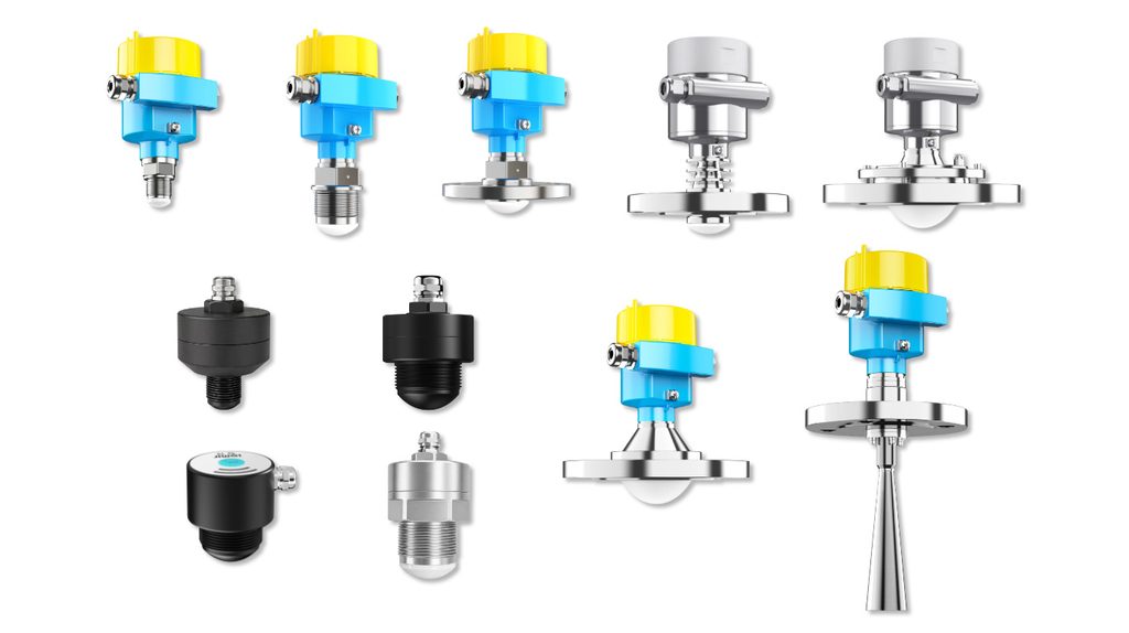
For compact and medium-size liquid vessels, an 80 GHz radar level meter can be attractive because the short wavelength supports a narrow beam and relatively small process connections.
Jiwei JWrada-31 is designed for conventional liquid measurement and compact process connections. For more demanding corrosive, high-temperature, larger, or complex applications, other JWrada models may be more appropriate.
The exact model should be selected after reviewing measuring range, antenna size, process connection, process temperature, process pressure, material compatibility, hazardous-area requirements, output signal, required enclosure material, and installation geometry.
A specification should never be selected solely from the product family name.
When Point Level Protection Should Be Added
A continuous radar transmitter can provide high-level alarms through the PLC or DCS, but a resin reactor may also benefit from a separate point level switch.
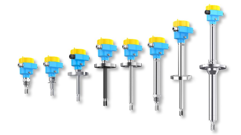
A tuning fork level switch installed at a defined high level can provide an independent switching signal for alarm or interlock logic.
This architecture can be especially useful where the process team wants a separate layer for overfill prevention.
For low-level protection, a point level switch can also help prevent a discharge or circulation pump from operating without sufficient liquid.
When using a tuning fork in viscous resin service, verify whether coating, viscosity, and temperature are within the suitable application range. The fork must be installed so that product can drain away and should not be positioned where the agitator creates excessive mechanical loading.
Installation Checklist for a Resin Reactor
Vessel geometry
Record the total height, diameter, bottom shape, nozzle position, nozzle length, and normal operating range.
Internal structures
Mark the agitator shaft, blades, coils, baffles, dip pipes, feed pipes, and cleaning devices.
Filling direction
Avoid mounting the sensor directly above a feed stream. Falling liquid can generate false reflections and can contaminate the antenna area.
Maximum level
Make sure the maximum operating level remains within the permitted near-range of the selected device and process connection.
Surface behavior
Identify whether the surface is calm, moderately turbulent, vortexed, or continuously foaming.
Cleaning
Confirm whether the reactor is washed with water, solvent, steam, or another cleaning medium.
Materials
Check the process-facing components against all raw materials, intermediates, by-products, and cleaning chemicals.
Commissioning Strategy
Commissioning should be performed under conditions that represent actual operation.
A useful approach is to record the radar echo profile when the vessel is empty or at a known low level, then again at one or more operating levels.
If fixed echoes appear from coils or agitator parts, they can be evaluated before the process reaches a critical level.
Next, verify the displayed level against a known reference. This could be a calibrated addition volume, vessel geometry, another trusted instrument, or a controlled fill test.
Finally, observe the signal during agitation and charging. If the value fluctuates, first determine whether the liquid surface itself is moving before changing instrument parameters.
Typical Benefits of a Correctly Engineered System
A well-applied radar level system can provide several practical advantages in resin production.
The non-contact principle reduces direct exposure of the sensor to sticky product. Continuous measurement gives operators visibility throughout the batch. A narrow beam can help the sensor work around internal structures. Digital communication and remote configuration can simplify commissioning where supported by the selected instrument.
The main benefit, however, is process visibility. Operators can see whether the vessel is charging as expected, whether the operating level remains within the desired range, and whether enough product remains for safe discharge.
What Not to Claim
When writing or specifying a reactor level system, avoid absolute statements such as “completely unaffected by foam,” “works in any reactor,” “no maintenance in all conditions,” “corrosion-proof for every chemical,” or “accurate regardless of installation.”
Industrial measurement always depends on application conditions.
A technically credible article should explain where the technology works well and what must be checked before selection.
Conclusion
Resin reactor level measurement is a system-engineering task. Agitators, foam, vapor, viscosity change, buildup, and internal metal structures can all affect the measurement environment.
Non-contact radar is often a strong option because it provides continuous measurement without inserting a probe into the reacting product. The best results come from combining a suitable radar model with a good mounting position, correct material selection, realistic signal settings, and verification under actual process conditions.
For reactors that also require an independent high- or low-level protection signal, a separate tuning fork level switch can complement the continuous radar transmitter.
FAQ
Can an 80 GHz radar level meter be used on an agitated resin reactor?
Yes, it can be suitable when the installation provides a clear measurement path and the process conditions are within the instrument limits. Agitator location, internal structures, foam, and maximum level should be reviewed before selection.
Does resin buildup affect radar?
Non-contact radar avoids immersing a probe in the resin, but buildup on the antenna area or process connection can still influence measurement. Installation and cleaning strategy remain important.
Where should a radar sensor be mounted on a reactor?
The sensor should have a clear view of the product surface and should avoid the filling stream, agitator shaft, major internal structures, and strong reflections from the tank wall.
Is a separate high-level switch necessary?
That depends on the plant’s control and safety philosophy. A continuous transmitter can generate alarms, but some applications use an independent point level switch as an additional protective layer.