
Natural gas produced from wells is rarely a single, clean gaseous medium that can be sent directly into a transmission pipeline. It often contains formation water, condensate, solid particles, and other liquid components. For this reason, gas-liquid separators, filter separators, cyclone separators, and other separation equipment are widely used throughout natural gas gathering, processing, purification, and transmission systems.
In these processes, stable liquid level control inside the separator directly affects both operating safety and separation efficiency. If the liquid level becomes too high, liquid may be carried into downstream equipment by the gas stream. If the level is too low, gas may enter the liquid discharge system and disrupt process control.
Reliable and accurate liquid level measurement is therefore an essential part of natural gas separator instrumentation.
Magnetic level gauges are widely suited to this application because they provide clear local indication without requiring power for basic display, while also supporting optional remote transmission and high/low level alarm functions.
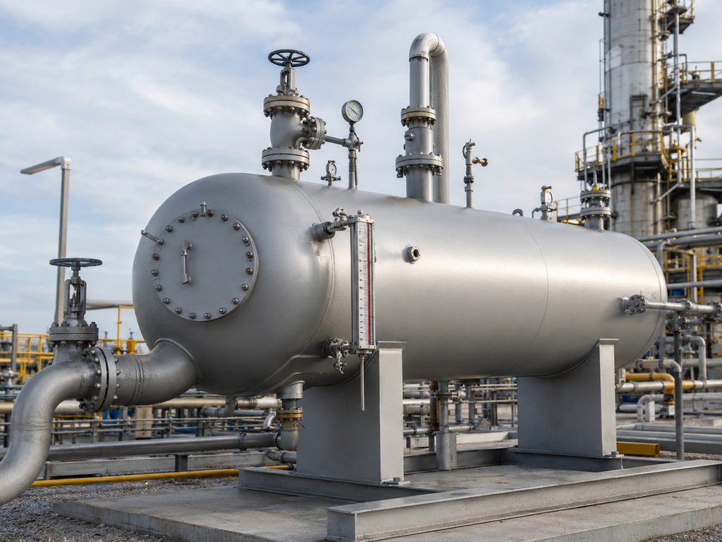
1. Why Accurate Level Measurement Is Essential in Natural Gas Separators
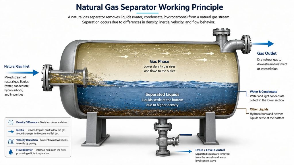
The primary function of a natural gas separator is to separate gas from liquid by utilizing differences in density, inertia, velocity, and flow behavior.
After separation, the gas exits from the upper section of the vessel and continues to downstream treatment or transmission processes. Separated water, condensate, and other liquids collect at the bottom of the separator and are discharged through a drain or level control system.
The liquid level must therefore remain within a controlled operating range.
If the liquid level is too high, the effective gas separation volume inside the vessel is reduced. As the level continues to rise, condensate or water that has already been separated may become re-entrained in the high-velocity gas stream, reducing separation efficiency.
In severe cases, liquid carryover may enter compressors, filters, pipelines, or downstream natural gas processing equipment.
If the liquid level is too low, gas may pass through the liquid outlet or enter the drain line. This can destabilize the level control loop and may introduce safety risks to downstream liquid handling equipment.
Natural gas separators are therefore commonly equipped with reliable level measuring devices, often combined with high-level, low-level, or high-high-level alarms for local indication, remote monitoring, and safety interlocking.
2. How a Magnetic Level Gauge Works
A magnetic level gauge operates primarily on the principles of communicating vessels and magnetic coupling.
The measuring chamber is connected to the natural gas separator through upper and lower process connections. As the liquid level inside the separator changes, the liquid level inside the external chamber rises or falls correspondingly according to the communicating vessel principle.
A magnetic float is installed inside the chamber. As the liquid level moves, the float travels vertically inside the chamber.
Permanent magnets inside the float generate a magnetic field that passes through the non-magnetic chamber wall and magnetically couples with the external indicator system.
The magnetic flaps, rollers, or flags on the indicator rotate as the float moves. The transition between two contrasting colors provides a clear visual indication of the actual liquid level inside the vessel.
One important advantage of this design is that the external level indicator does not come into direct contact with the process medium.
Under normal operating conditions, personnel can determine the separator liquid level without opening the vessel or directly viewing the pressurized process fluid.
3. Why Magnetic Level Gauges Are Suitable for Natural Gas Separators
3.1 Clear and Easy-to-Read Local Indication
Natural gas stations and processing facilities typically contain a large number of vessels, pipelines, valves, and instruments. Field operators need to assess equipment conditions quickly during inspections.
A magnetic level gauge provides direct visual indication using highly visible contrasting colors.
With a wide indicator panel, the liquid level can often be identified from a greater viewing angle and distance, making the instrument particularly useful for filter separators, gas-liquid separators, and other vessels requiring routine field inspection.
3.2 Local Level Indication Without External Power
The local display of a magnetic level gauge operates through buoyancy and magnetic coupling and does not require an external electrical power supply.
This means that even if the control system temporarily loses power, operators can still observe the actual separator liquid level locally.
For this reason, magnetic level gauges can serve either as the primary local level indicator or as an independent reference device used to verify electronic level instruments.
3.3 Capability for High-Pressure Applications
Natural gas separators are typically pressure vessels. In gathering stations, gas processing plants, and pipeline facilities, they may operate under relatively high pressure.
The liquid level instrument must therefore be designed with appropriate chamber wall thickness, process connections, flange pressure ratings, float strength, welding quality, and pressure resistance.
Industrial magnetic level gauges may use seamless 316L stainless steel chambers, with wall thickness selected according to process pressure and temperature.
Certain configurations can cover process pressures from vacuum conditions up to approximately 10 MPa, allowing them to be applied in a wide range of natural gas operating conditions.
However, instrument selection should never be based only on the maximum allowable pressure of the level gauge.
The actual design must consider the separator design pressure, operating pressure, design temperature, process medium, flange standard, and applicable engineering specifications.
3.4 Suitable for Hazardous Areas
Natural gas is flammable and potentially explosive. Instrumentation used in gas processing facilities must therefore comply with hazardous-area requirements.
A basic mechanical magnetic level gauge does not depend on electrical sensing for local indication.
When magnetic switches or remote level transmitters are installed, however, the electrical accessories must be selected according to the hazardous-area classification of the installation site.
Explosion-proof or intrinsically safe versions may be used, including protection concepts such as Ex d IIC T6 Gb or Ex ia IIC T6 Ga, depending on plant design and safety requirements.
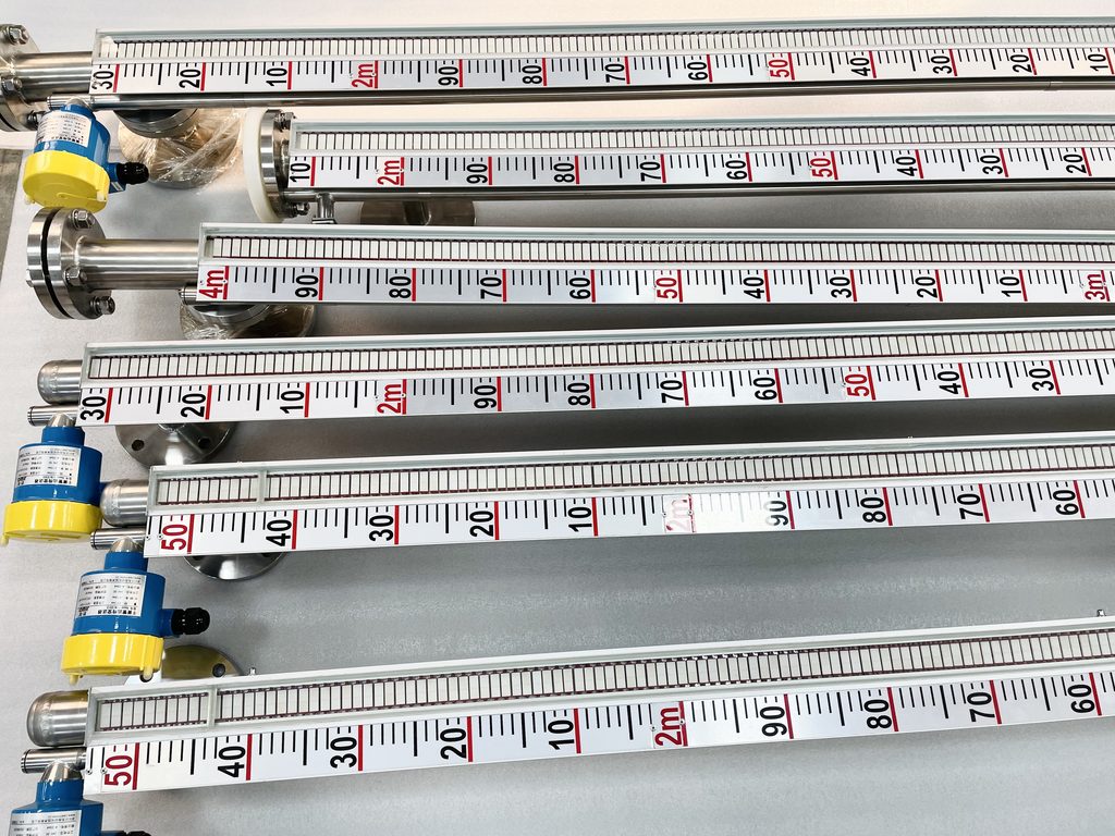
4. Combining Local Indication with Remote Level Monitoring
Modern natural gas facilities rarely rely exclusively on manual field readings. Liquid level signals are generally required in a DCS, PLC, SCADA, or other process control system.
A magnetic level gauge can therefore be equipped with a reed-chain level transmitter or similar remote transmission device.
As the magnetic float moves with the liquid level, its magnetic field changes the state of corresponding reed switches inside the transmitter.
This produces an electrical resistance value related to the float position, which can then be converted into a standard 4–20 mA level output signal.
The measuring chain can be represented as:
Actual separator liquid level → magnetic float position → electrical signal conversion → 4–20 mA output → control room level indication
Operators can therefore read the level directly in the field while also monitoring the same process variable continuously from a central control room.
Some transmitter configurations may also support 4–20 mA with HART communication, providing additional capabilities for digital instrument management, commissioning, and diagnostics.
This combination of local mechanical indication and continuous remote transmission is one of the main reasons magnetic level gauges are widely used on natural gas separators.
5. The Role of High and Low Level Alarms
For natural gas separation equipment, knowing the current liquid level alone is not always sufficient.
Abnormal level conditions must often be detected before they develop into process or safety incidents.
Magnetic level gauges can be equipped with externally mounted magnetic level switches.
When the magnetic float reaches a preset position, its magnetic field activates the level switch and generates a discrete electrical output.
Depending on process requirements, the system may include:
- A high-level alarm to indicate that additional liquid drainage is required.
- A high-high-level alarm for emergency shutdown or safety interlocking.
- A low-level alarm to prevent excessive liquid removal.
- A low-low-level alarm to protect the discharge system or initiate specific control actions.
By combining a magnetic level gauge, level transmitter, and magnetic switches, the system can provide local indication, continuous remote measurement, and high/low level alarm functions.
For applications with higher safety integrity requirements, the instrument configuration should also be evaluated together with the Safety Instrumented System, or SIS.
Independent alarms, shutdown functions, and safety loops should be designed according to the required safety integrity level rather than relying on a single level sensing element for all protection functions.
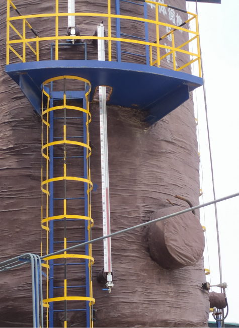
6. How to Select a Magnetic Level Gauge for a Natural Gas Separator
Selecting a separator level gauge involves much more than simply choosing a measuring range.
Several process parameters are especially important.
6.1 Liquid Density
The magnetic float is designed according to the density of the process liquid.
The liquid phase inside a natural gas separator may consist of water, condensate, hydrocarbon mixtures, produced water, or combinations of these fluids. Their densities can vary significantly.
If the float is not correctly matched to the process density, insufficient buoyancy may cause measurement error or prevent proper float movement.
For this reason, both the normal operating density and the minimum expected liquid density should be provided during instrument selection.
6.2 Operating and Design Pressure
Because the separator is a pressurized vessel, the magnetic level gauge chamber effectively becomes part of the process pressure boundary.
Instrument selection should therefore consider normal operating pressure, maximum operating pressure, design pressure, flange rating, chamber material, wall thickness, and welding structure.
For higher-pressure services, seamless chamber construction and properly engineered pressure ratings are particularly important for reducing the risk of leakage during long-term operation.
6.3 Operating Temperature
Temperature affects not only the chamber material but also fluid density, float buoyancy, seals, and external indicator components.
Industrial magnetic level gauges can be designed for a wide temperature range, with some configurations suitable for approximately -40°C to 350°C.
Nevertheless, the actual instrument should always be selected according to the real operating and design temperatures of the natural gas process.
Maximum published ratings should not be used as a substitute for proper engineering verification.
6.4 Wetted Materials
The composition of condensate and produced water in natural gas systems can be complex and may contain corrosive components.
For general applications, 304 or 316L stainless steel may be selected depending on fluid characteristics.
Where the process medium is more corrosive, lined chambers or alternative corrosion-resistant materials may be required.
Among common options, 316L stainless steel offers good overall corrosion resistance and is frequently used in natural gas, petrochemical, and chemical liquid level applications.
6.5 Measuring Range
The measuring range should be selected according to the upper and lower process connection positions on the separator and the actual level range that must be monitored.
Some standard magnetic level gauge configurations can provide a single-section measuring range of approximately 200 to 5600 mm. Longer ranges may require segmented or customized designs.
An important engineering consideration is that the flange center-to-center distance is not always identical to the full effective indication range.
The zero point, full-scale position, process nozzle locations, and vessel dimensions should all be verified against the equipment drawing.
7. Installation Considerations for Natural Gas Separator Applications
Correct installation has a direct effect on the long-term reliability of a magnetic level gauge.
First, the level gauge should be installed vertically so that the magnetic float can move freely inside the chamber.
If the chamber is tilted, the float may rub against the chamber wall and could eventually stick.
Second, isolation valves are recommended between the separator and the upper and lower process connections of the level gauge.
This allows the instrument to be isolated for inspection, draining, cleaning, or maintenance without necessarily shutting down the entire separator.
Third, strongly magnetic or ferromagnetic materials should be kept away from the level indicator whenever possible.
External magnetic interference can affect the interaction between the float and the indicator flags.
Mounting components and nearby structures should therefore be designed to minimize interference with the magnetic field.
Fourth, when the instrument includes a transmitter, magnetic switches, or other electrical accessories, cable entry, grounding, sealing, and environmental protection should comply with hazardous-area installation practices.
Fifth, during initial commissioning, process liquid should not be introduced into the chamber at excessive velocity.
A preferred procedure is to establish gas-side communication first and then gradually open the liquid-side isolation valve.
This allows the chamber to fill smoothly and helps prevent rapid float movement, which could cause irregular flag rotation or temporary indication errors.
8. Why Draining and Cleaning Are Important
The liquid collected in a natural gas separator is not necessarily clean.
Condensate, produced water, scale, sand, corrosion products, and other solid particles may gradually enter the external level chamber.
If solids accumulate at the bottom of the chamber, they can restrict float movement and eventually cause sluggish indication or complete float blockage.
For this reason, magnetic level gauges used on natural gas separators should generally include suitable draining and cleaning provisions.
Maintenance intervals can be established according to fluid cleanliness, separator drain frequency, operating experience, and contamination history.
Routine inspection should focus on:
- Whether the float moves freely.
- Whether the drain connection is blocked.
- Whether the magnetic display changes continuously.
- Whether flanges and valves show signs of leakage.
- Whether local indication agrees with the remote level signal.
- Whether high and low level switches operate correctly.
For filter separators or process vessels handling liquids with higher concentrations of solids, more frequent draining and inspection can significantly reduce the risk of float sticking and incorrect level indication.
9. Common Magnetic Level Gauge Problems and Troubleshooting
9.1 Discontinuous or Incorrect Flag Indication
If some magnetic flags display the wrong color or appear out of sequence, possible causes include rapid level changes, mechanical vibration, or interference from an external magnetic field.
Where necessary, the indicator can be reset using the appropriate magnetic tool according to the manufacturer’s instructions.
9.2 Local Level Indication Does Not Change
A constant local reading does not necessarily mean the actual separator level is stable.
The technician should check whether the upper and lower process connections are blocked, whether the isolation valves are fully open, and whether the magnetic float is trapped by deposits.
In natural gas separation systems containing contaminated liquids or solid particles, deposits at the bottom of the chamber should be considered a primary troubleshooting point.
9.3 Local Display and Remote Signal Do Not Match
If the magnetic level display is operating normally but the 4–20 mA signal in the control room is incorrect, the inspection should focus on the remote transmitter, wiring, power supply, installation position, zero setting, and span configuration.
If the remote level signal changes correctly but the local flags remain stationary, the external indicator, float magnetic coupling, and potential magnetic interference should be checked.
Comparing the local indication with the remote transmitter signal is often an effective way to identify the part of the measuring system where the fault has occurred.
10. Application Value of Magnetic Level Gauges in the Natural Gas Industry
As automation continues to expand throughout natural gas gathering, processing, and transmission systems, level instruments are expected to do more than simply indicate liquid height.
They increasingly contribute to alarm systems, drainage control, process automation, and safety shutdown functions.
For a natural gas separator, an effective level measurement solution must balance pressure resistance, local readability, hazardous-area compliance, remote transmission capability, maintainability, and long-term operating reliability.
Magnetic level gauges use buoyancy and magnetic coupling to provide clear local indication while supporting optional 4–20 mA transmitters and high/low level switches.
When the wetted material, pressure rating, float density, process connection, measuring range, and explosion protection method are properly selected, the instrument can provide reliable level monitoring for a wide variety of natural gas separation applications.
However, natural gas separators are often pressure vessels operating in hazardous environments. A level gauge should therefore never be selected solely on the basis of connection size, measuring range, or purchase price.
For proper engineering selection, the following process information should normally be provided:
process medium and composition, liquid density, design pressure, design temperature, operating pressure, operating temperature, measuring range, flange standard, hazardous-area requirements, and the need for remote transmission or level alarms.
Only when the instrument is correctly selected for the process conditions—and installed, commissioned, drained, and inspected according to appropriate procedures—can a magnetic level gauge provide stable long-term performance on a natural gas separator.
A properly engineered system can deliver reliable local level indication, continuous remote monitoring, and alarm functions, helping support the safe, stable, and efficient operation of natural gas processing facilities.

