
1. Project Background
In chemical production, storage tank level is a critical parameter that affects operational safety, material management, and process stability. An excessively high liquid level may cause overflow, environmental contamination, material loss, or serious safety incidents. An excessively low liquid level may result in pump dry running, production interruption, or equipment damage.
For this reason, selecting a reliable and clearly readable liquid level instrument is an important part of chemical plant automation and storage tank safety management.
This application case comes from a fine chemical manufacturing company. The plant operates several raw material storage tanks and intermediate product tanks containing organic solvents, acidic and alkaline solutions, and various volatile chemical materials.
The original liquid level measurement system mainly relied on glass tube level gauges and manual inspection. Operators had to approach each tank to check the liquid level visually. After long-term operation, the glass tube gauges gradually developed problems such as aging seals, broken glass tubes, unclear readings, and chemical leakage.
To improve measurement safety and increase the level of process automation, the company decided to upgrade six chemical storage tanks. After analyzing the operating conditions and comparing several liquid level measurement technologies, the project team selected side-mounted magnetic level gauges equipped with remote level transmitters.

2. Main Challenges in Chemical Storage Tank Level Measurement
Liquid level measurement in a chemical storage tank is more demanding than level measurement in an ordinary water tank. The properties of the chemical medium, operating temperature, pressure, corrosion level, viscosity, and explosion-proof requirements can all affect instrument selection.
2.1 Corrosive Chemical Media
Some tanks in this project were used to store acidic solutions and alkaline cleaning liquids. If the wetted parts of the level gauge were made from unsuitable materials, long-term contact with the chemical medium could result in corrosion, perforation, seal failure, and leakage.
Therefore, the chamber, float, flanges, valves, and sealing materials of the magnetic level gauge had to be selected according to the exact chemical composition of the medium.
For mildly corrosive liquids, 304 or 316L stainless steel may be suitable. For highly corrosive acids, alkalis, or chloride-containing liquids, PTFE lining, polypropylene, PVC, titanium, or other corrosion-resistant materials may be required.
Material selection should never be based only on a general description such as “acid,” “alkali,” or “chemical liquid.” The chemical concentration, temperature, pressure, and compatibility of all wetted materials must also be considered.
2.2 Closed and Pressurized Storage Tanks
Several storage tanks operated under slight positive pressure, and some of the stored chemicals were volatile.
Traditional open-type level measurement methods could allow vapors to escape into the surrounding environment. This would increase safety risks and make it more difficult to control workplace emissions.
A magnetic level gauge uses a sealed chamber connected to the storage tank through process flanges. It can display the liquid level without opening the tank or exposing the liquid directly to the environment. This makes it suitable for closed tanks, pressurized vessels, separators, and other chemical process equipment.
2.3 Requirement for Remote Level Monitoring
The chemical company wanted operators to read the tank level locally while also monitoring it continuously from the central control room.
The system also needed to generate alarms when the liquid reached a high-level or low-level limit.
For this reason, the selected magnetic level gauges were equipped with:
- Local magnetic flap or magnetic roller indication;
- A 4–20 mA remote level transmitter;
- A high-level alarm switch;
- A low-level alarm switch;
- Signal output to the plant DCS.
This configuration provided local indication, remote transmission, trend monitoring, and alarm functions in one integrated level measurement system.
2.4 Limited Installation Space
Some storage tanks were surrounded by process pipelines, valves, platforms, ladders, and other equipment. The available installation space was limited.
The overall length of the magnetic level gauge, flange center distance, drain valve direction, transmitter position, and indicator viewing direction all had to be carefully confirmed before production.
Before manufacturing the instruments, the technical team checked the following site dimensions:
- Distance between the upper and lower tank nozzles;
- Flange size and pressure rating;
- Flange standard;
- Installation orientation;
- Available maintenance space;
- Display panel direction;
- Cable entry direction;
- Drain and vent requirements.
This preliminary confirmation prevented installation problems after the instruments arrived on site.
3. Why a Magnetic Level Gauge Was Selected
A magnetic level gauge is also known as a magnetic float level gauge, magnetic flap level gauge, or magnetic bypass level indicator.
Its operating principle is based on buoyancy and magnetic coupling.
The measuring chamber is connected to the storage tank. Because the chamber and the tank form a communicating vessel, the liquid level inside the chamber follows the level inside the tank.
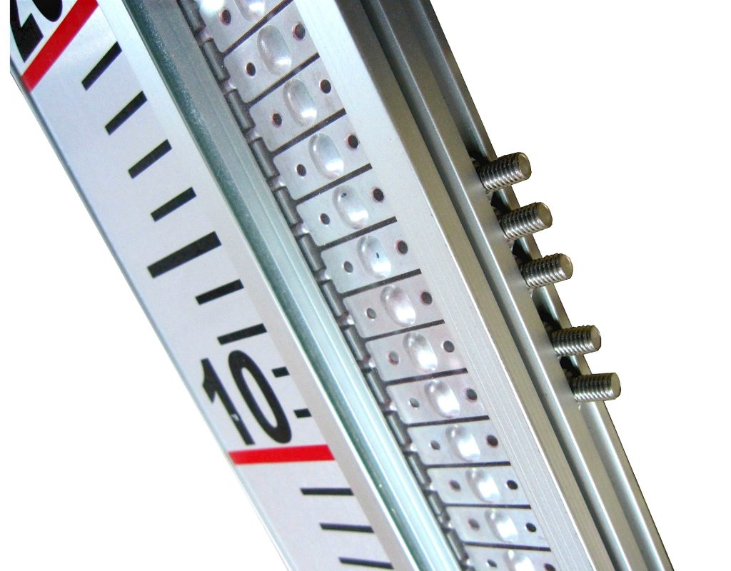
A float containing a magnetic assembly moves upward or downward as the liquid level changes. The magnetic field inside the float activates the external magnetic flaps, rollers, or flags. These indicators rotate and change color, showing the actual liquid level clearly.
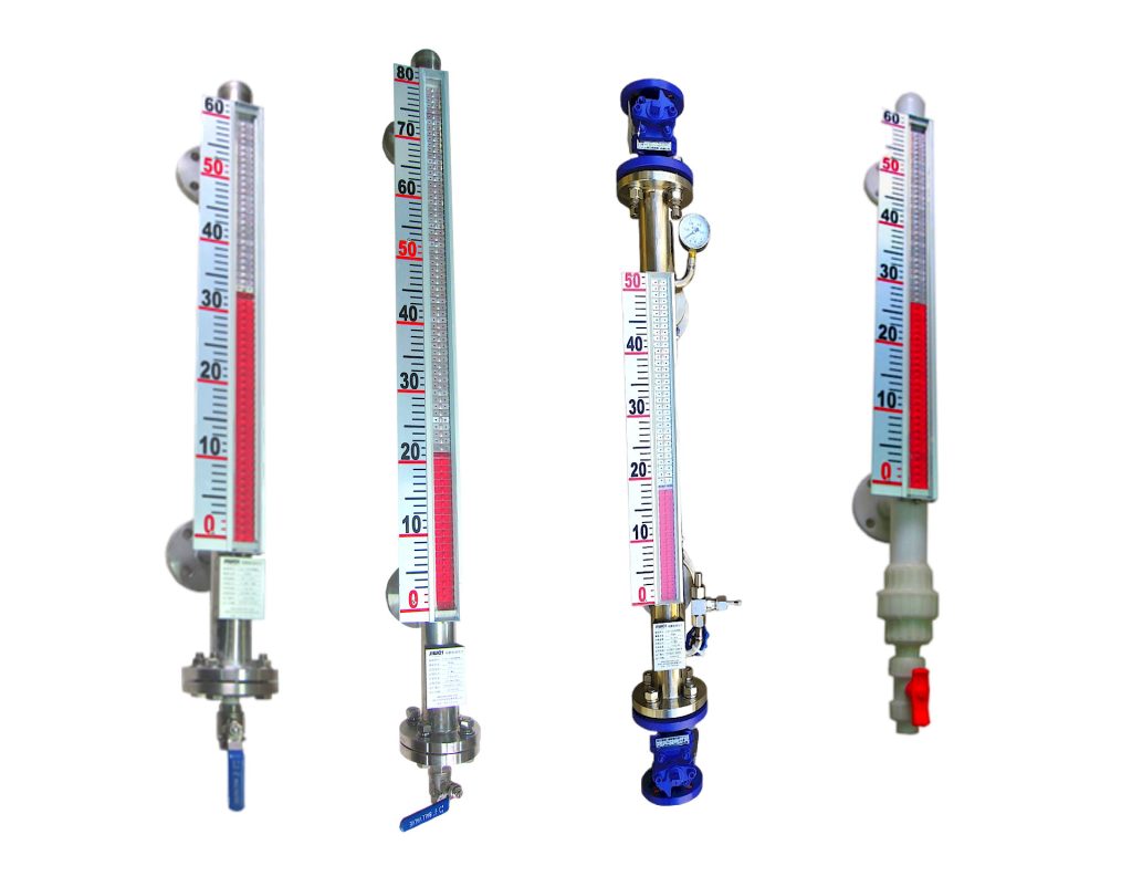
The display system does not come into direct contact with the process liquid.
Compared with a traditional glass tube level gauge, a magnetic level gauge offers several advantages:
- Clear and highly visible local level indication;
- Sealed measuring structure;
- Reduced risk of chemical leakage;
- No external power supply required for local indication;
- Optional 4–20 mA remote signal output;
- Optional high- and low-level alarm switches;
- Multiple corrosion-resistant material options;
- Suitable for tanks, reactors, separators, boilers, and pressure vessels;
- Relatively low routine maintenance requirements;
- Easy integration with PLC and DCS systems.
Because this project required local indication, remote monitoring, and alarm output, the magnetic level gauge provided a more complete solution than a basic mechanical or glass level indicator.
4. Storage Tank Operating Conditions
The following parameters describe one representative raw material storage tank in this project:
- Tank type: vertical closed storage tank;
- Tank capacity: approximately 30 cubic meters;
- Measuring range: 0–3200 mm;
- Medium: organic chemical raw material;
- Medium density: approximately 0.92 g/cm³;
- Operating temperature: ambient temperature to 80°C;
- Operating pressure: below 0.4 MPa;
- Installation type: side-mounted;
- Process connection: flanged connection;
- Flange size: DN25;
- Chamber material: 316L stainless steel;
- Output signal: 4–20 mA;
- Alarm requirement: high-level and low-level alarms;
- Installation environment: outdoor chemical plant;
- Electrical requirement: explosion-proof accessories selected according to the hazardous area classification.
Liquid density is one of the most important parameters when selecting a magnetic float level gauge.
The size, weight, wall thickness, and internal structure of the float must be designed according to the actual density of the process liquid. If the liquid density is too low, a standard float may not generate sufficient buoyancy.
For reliable operation, the manufacturer should receive the actual liquid density at the lowest possible operating temperature.
5. Magnetic Level Gauge Selection
5.1 Installation Type
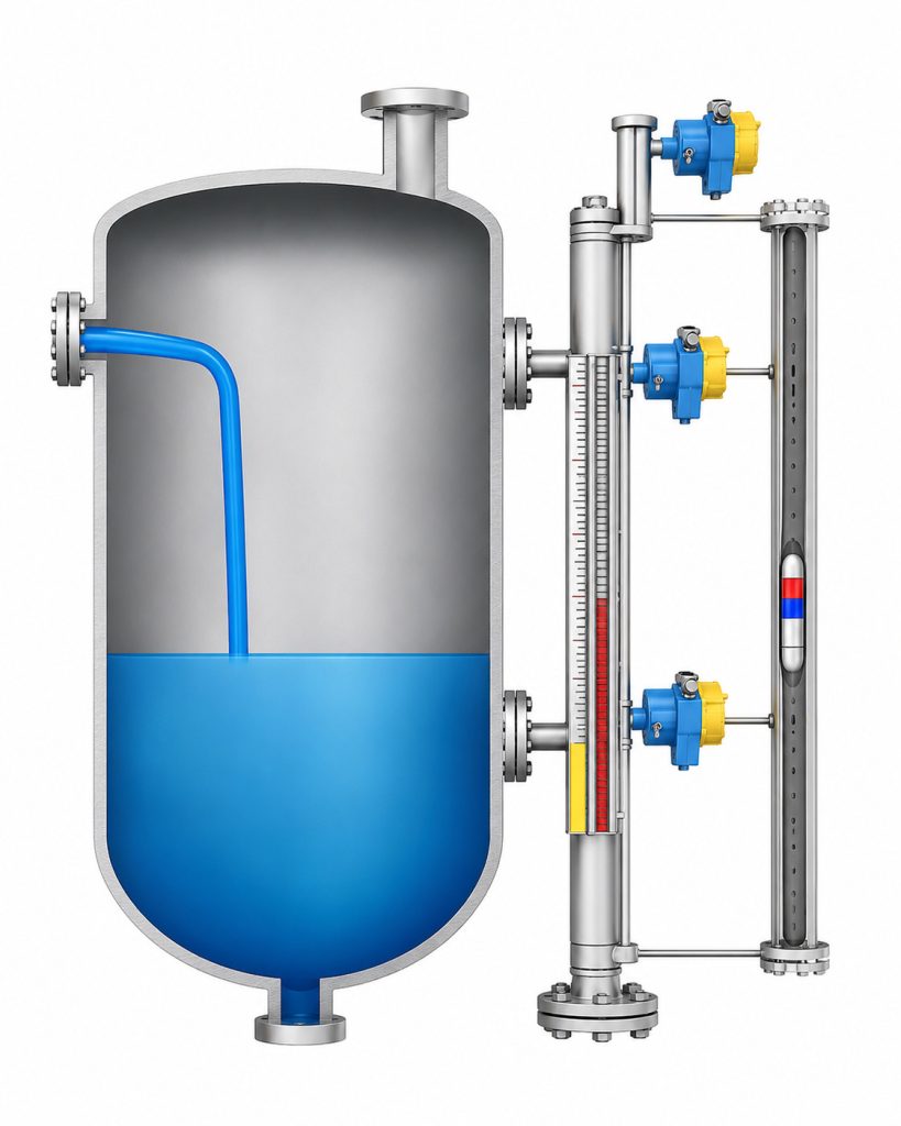
Based on the tank structure and the existing process nozzles, the project used side-mounted magnetic level gauges.
The upper and lower process flanges of each level gauge were connected to the corresponding side nozzles on the storage tank. This created a bypass chamber that followed the liquid level inside the tank.
Side-mounted magnetic level gauges are suitable for many vertical storage tanks. They provide convenient local observation and allow easy installation of drain valves, alarm switches, and remote transmitters.
For tanks without side connections, a top-mounted magnetic level gauge may be considered. However, top-mounted instruments usually require a customized float, guide structure, connecting rod, or chamber arrangement.
The tank height, internal obstructions, liquid turbulence, available roof space, and maintenance requirements must be evaluated before selecting a top-mounted design.
5.2 Wetted Material Selection
Because the stored medium had a moderate level of corrosiveness, the chamber, connecting flanges, float, and drain components were manufactured from 316L stainless steel.
Compared with standard 304 stainless steel, 316L stainless steel offers better corrosion resistance in many chemical applications.
However, 316L is not suitable for every corrosive medium. It may not provide adequate resistance to certain hydrochloric acid solutions, high-concentration sulfuric acid, strong alkalis, chloride-rich liquids, or highly aggressive chemical mixtures.
For more severe applications, the following materials may be considered:
- PTFE-lined stainless steel;
- Polypropylene;
- PVC;
- PVDF;
- Titanium;
- Hastelloy;
- Other special alloys.
Final material selection should be based on the exact chemical composition, concentration, operating temperature, pressure, and expected service life.
5.3 Float Design
The technical team selected the float according to the liquid density, operating temperature, and maximum process pressure.
The float needed to provide sufficient buoyancy while also resisting pressure deformation and chemical corrosion.
If the liquid is highly viscous, crystallizing, polymerizing, or contains a large quantity of solid particles, the float may become stuck inside the chamber.
For such applications, possible solutions include:
- Increasing the chamber diameter;
- Using a specially designed float;
- Adding heat tracing or insulation;
- Installing flushing connections;
- Increasing drain frequency;
- Selecting another level measurement technology.
A magnetic level gauge should not be selected automatically for every chemical liquid. The tendency of the medium to coat, crystallize, or deposit solids must be evaluated carefully.
5.4 Remote Level Transmitter
A magnetic sensing level transmitter was mounted externally along the measuring chamber.
As the magnetic float moved with the liquid level, the transmitter detected the magnetic field position and converted it into a standard 4–20 mA current signal.
The signal was connected to the plant DCS, allowing operators to view:
- Real-time tank level;
- Historical level trends;
- Filling and discharge rates;
- High- and low-level conditions;
- Abnormal level changes.
During commissioning, 4 mA was configured to represent the lower level limit, while 20 mA represented the upper level limit.
The measuring range in the DCS was then set to 0–3200 mm to match the actual instrument range.
For hazardous areas, the transmitter had to meet the required explosion-proof or intrinsically safe certification requirements.
5.5 High- and Low-Level Alarm Switches
Two magnetic alarm switches were installed on the outside of the level gauge chamber.
One switch was used for high-level alarm, while the other was used for low-level alarm.
When the float reached the preset position, its magnetic field activated the corresponding switch. The switch then sent a discrete signal to the control system.
The high-level alarm warned operators to stop or reduce tank filling. The low-level alarm helped prevent the transfer pump from running dry.
Depending on the process design, the alarm signal could also be used for automatic interlocking. For example, the high-level switch could close an inlet valve, while the low-level switch could stop a discharge pump.
Alarm switch positions can be adjusted according to process requirements. After any adjustment, the alarm point must be tested again to confirm that the signal corresponds to the actual liquid level.
6. On-Site Installation Process
After the magnetic level gauges arrived at the plant, the installation team checked the instruments before mounting them.
The inspection included:
- Overall appearance;
- Measuring range;
- Flange specification;
- Chamber material;
- Float direction;
- Indicator orientation;
- Transmitter model;
- Alarm switch quantity;
- Drain valve configuration;
- Nameplate information.
The installation process was completed as follows.
First, the tank connection flanges were cleaned. The sealing surfaces were checked for corrosion, scratches, deformation, and foreign material.
Second, the magnetic level gauge was installed vertically on the side of the storage tank. Vertical alignment is important because excessive inclination may prevent the float from moving freely.
Third, gaskets compatible with the chemical medium, pressure, and temperature were installed. The flange bolts were tightened gradually and evenly.
Fourth, the float installation direction was confirmed. Some floats have a clearly defined top and bottom. An incorrectly installed float may fail to rise properly or may not activate the magnetic indicator.
Fifth, the level transmitter and alarm switch cables were connected. Wiring in hazardous chemical areas was completed according to the site’s explosion-proof electrical requirements.
Sixth, the isolation valves between the tank and the magnetic level gauge were opened slowly. This allowed the process liquid to enter the chamber gradually.
Opening the valves too quickly could create a pressure surge and cause the float to move violently, which might lead to incorrect indication or damage.
Seventh, the team tested the local display, remote signal, alarm switches, and flange connections.
A drain valve was installed at the bottom of the chamber to support future maintenance. Depending on the cleanliness of the process liquid, operators could periodically remove deposits from the bottom of the chamber.
7. Problems Found During Commissioning
During initial filling, the local magnetic indicator worked correctly, but the liquid level displayed in the control room showed a small deviation from the actual level.
After inspection, the technical team found that the range configured in the DCS did not match the measuring range of the magnetic level gauge.
The DCS range was corrected to 0–3200 mm, and the 4 mA and 20 mA points were verified again. After recalibration, the remote level reading matched the local indication.
On another storage tank, several magnetic flaps on the display panel did not show a consistent color after installation.
The team checked the float movement and confirmed that it was not stuck. The problem was caused by several indicator flaps changing orientation during transportation and installation.
A magnetic reset tool was moved upward along the display panel. This restored the flaps to the correct orientation, and the indicator returned to normal operation.
These commissioning issues showed that the local display alone should not be considered sufficient evidence of correct installation.
After installation, the following items should be tested:
- Whether the magnetic indicator changes continuously;
- Whether the float moves freely;
- Whether the remote signal matches the actual level;
- Whether the high-level alarm activates at the correct position;
- Whether the low-level alarm activates at the correct position;
- Whether the DCS range is configured correctly;
- Whether process flanges, drain valves, and instrument connections are leak-free.
8. Operating Results
After the upgrade, all six chemical storage tank level measurement systems operated continuously and remained stable.
First, operators could identify the tank level directly from the clear color change on the magnetic indicator. They no longer needed to approach fragile glass tubes or read small and unclear scales. This improved inspection efficiency and reduced operator exposure to the process area.
Second, the level signals were transmitted to the central control room. Operators could monitor the filling and discharge processes in real time.
When the level approached the upper limit, the control system generated an alarm. This reduced the risk of overfilling, overflow, product loss, and environmental contamination.
Third, the low-level alarm was incorporated into the transfer pump operating logic. When the liquid reached the low-level limit, operators received a warning before the pump ran dry.
Fourth, the sealed magnetic level gauge eliminated the fragile glass tube used in the original system. This reduced the number of potential leakage points and lowered routine maintenance requirements.
The project demonstrated that a properly selected magnetic level gauge can meet several requirements at the same time:
- Clear local level indication;
- Reliable remote level transmission;
- High- and low-level alarm output;
- Safer measurement of closed chemical tanks;
- Reduced manual inspection;
- Improved storage tank management.
9. Important Selection Factors for Chemical Storage Tanks
To ensure reliable long-term performance, users should provide complete operating condition information when requesting a quotation or selecting a magnetic level gauge.
9.1 Specify the Exact Process Medium
A description such as “chemical liquid” is not sufficient for accurate selection.
The following information should be provided:
- Chemical name;
- Chemical concentration;
- Corrosiveness;
- Toxicity;
- Flammability;
- Volatility;
- Crystallization tendency;
- Polymerization tendency;
- Presence of suspended solids.
This information helps determine chamber material, float design, gasket material, and suitable accessories.
9.2 Provide the Liquid Density
Liquid density directly affects the float design.
This is especially important for low-density organic solvents and hydrocarbons. The manufacturer should know the minimum possible density under actual operating conditions.
Density may change as temperature changes. Therefore, the density at the lowest operating temperature should be considered.
9.3 Confirm Operating Temperature and Pressure
The chamber, float, flanges, gaskets, transmitter, and switches must all be suitable for the maximum operating temperature and pressure.
Selection should not be based only on normal operating values. Possible process fluctuations, startup conditions, cleaning cycles, and maximum design conditions should also be considered.
9.4 Confirm Measuring Range and Flange Center Distance
For a side-mounted magnetic level gauge, the measuring range is usually related to the center-to-center distance between the upper and lower tank connections.
Accurate dimensional information must be provided before manufacturing. Incorrect dimensions may prevent the level gauge flanges from aligning with the tank nozzles.
9.5 Evaluate Crystallization, Adhesion, and Viscosity
Highly viscous, crystallizing, polymerizing, or particle-containing liquids may restrict float movement.
Depending on the application, the instrument may require:
- A larger chamber diameter;
- Steam or electric heat tracing;
- Thermal insulation;
- Flushing connections;
- Regular draining and cleaning;
- A specially designed float.
In severe cases, radar, guided wave radar, differential pressure, or another level measurement method may be more appropriate.
9.6 Confirm Explosion-Proof Requirements
The local magnetic indicator normally operates without electrical power.
However, when a remote transmitter or alarm switch is added, the electrical components must match the hazardous area classification of the installation site.
The correct explosion protection method, electrical connection, cable gland, grounding arrangement, and safety barrier should be determined according to the plant’s engineering requirements.
10. Routine Maintenance Recommendations
Although magnetic level gauges have a relatively simple structure, they still require periodic inspection.
Operators should check:
- Whether the display is continuous and clear;
- Whether the remote signal is stable;
- Whether local and remote readings are consistent;
- Whether the flanges are leaking;
- Whether the drain valve is sealed;
- Whether the alarm switches operate correctly;
- Whether the chamber contains deposits.
For liquids that produce sediment, the bottom drain valve should be opened periodically according to the plant’s maintenance procedure.
Before removing the level gauge, operators must close the upper and lower isolation valves between the instrument and the storage tank.
The chamber must then be depressurized and drained. Any remaining chemical liquid must be handled according to the plant’s safety procedures.
The instrument must never be disassembled while the tank is pressurized or while hazardous liquid remains inside the chamber.
For toxic, flammable, volatile, or corrosive chemicals, appropriate personal protective equipment, process isolation, purging, gas testing, and site supervision are required.
11. Frequently Asked Questions
What types of chemical liquids can a magnetic level gauge measure?
A magnetic level gauge can be used for many liquids, including water, oil, organic solvents, acidic solutions, alkaline solutions, and chemical raw materials.
However, suitability depends on liquid density, corrosion level, viscosity, temperature, pressure, solids content, and crystallization characteristics.
Can a magnetic level gauge provide a 4–20 mA output?
Yes. An external magnetic sensing level transmitter can convert the float position into a 4–20 mA signal.
The signal can be connected to a PLC, DCS, display controller, recorder, or other automation system.
Can a magnetic level gauge be used in an explosion-hazardous area?
Yes, provided that the electrical accessories are selected correctly.
The basic local indicator does not normally require power. However, remote transmitters and alarm switches used in hazardous areas must have appropriate explosion-proof or intrinsically safe protection.
Why does a magnetic level gauge sometimes show an interrupted display?
Possible causes include:
- A stuck float;
- Incorrect float installation;
- Misaligned magnetic flaps;
- Deposits inside the chamber;
- Excessive instrument inclination;
- A float that is unsuitable for the liquid density;
- Strong external magnetic interference.
The local indication, remote output, chamber condition, and float movement should be checked systematically.
What material should be used for highly corrosive chemicals?
The correct material depends on the chemical name, concentration, temperature, and pressure.
Possible options include 316L stainless steel, PTFE lining, polypropylene, PVC, PVDF, titanium, Hastelloy, or another special alloy.
Material compatibility should be confirmed using accurate process data rather than a general description of the liquid.
Can a magnetic level gauge control a pump or valve?
The level gauge itself provides measurement and switch signals.
When connected to a PLC, DCS, relay, or control panel, the high- and low-level switches can be used to start or stop pumps, open or close valves, or activate alarms.
The final control logic should be designed according to the plant’s safety requirements.
12. Conclusion
This project used side-mounted magnetic level gauges to solve several problems associated with the original chemical storage tank level measurement system.
The upgrade improved local visibility, removed fragile glass tube components, enabled remote level monitoring, and added high- and low-level alarms.
The application results show that magnetic level gauges are particularly suitable for chemical storage tanks that require:
- Clear local indication;
- Sealed level measurement;
- Remote signal transmission;
- High- and low-level alarms;
- Integration with PLC or DCS systems;
- Reduced manual inspection;
- Improved process safety.
However, a magnetic level gauge should not be selected only according to the measuring range.
Liquid density, chemical compatibility, operating temperature, pressure, viscosity, crystallization tendency, flange standard, installation space, and explosion-proof requirements must all be confirmed during the engineering stage.
Only a magnetic level gauge designed according to the actual process conditions can provide reliable, safe, and stable long-term operation in a chemical storage tank application.

