
Dual relay outputs are widely used in industrial automation, level control, pump operation, equipment alarms and safety interlock systems. They are commonly found in level meters, level switches, pressure controllers, temperature controllers and other process instruments.
For users who are new to industrial instrumentation, several questions often arise:
What does “dual relay output” mean? How is it different from a single relay output? Can two relays control two separate devices? How should the COM, NO and NC terminals be connected?
In simple terms, a dual relay output means that an instrument or controller contains two independently controlled relay output channels.
Each relay can be configured to activate or deactivate when a specified condition is reached. The relay contacts can then control an alarm lamp, buzzer, contactor, pump, solenoid valve, programmable logic controller or another external device.
In level measurement applications, dual relay outputs are frequently used for high- and low-level alarms, upper- and lower-limit control, pump start and stop operation, or equipment safety interlocks.
1. What Is a Relay?
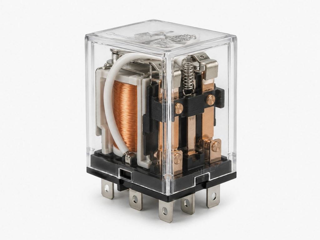
A relay is an electrical switching device that allows a relatively small control signal to switch another electrical circuit.
It can be understood as an automatically operated switch. When the relay receives the required control signal, its internal contacts change position. When the control signal is removed, the contacts return to their normal state.
A conventional electromechanical relay typically includes:
- A coil or electronic driver circuit
- An electromagnetic switching mechanism
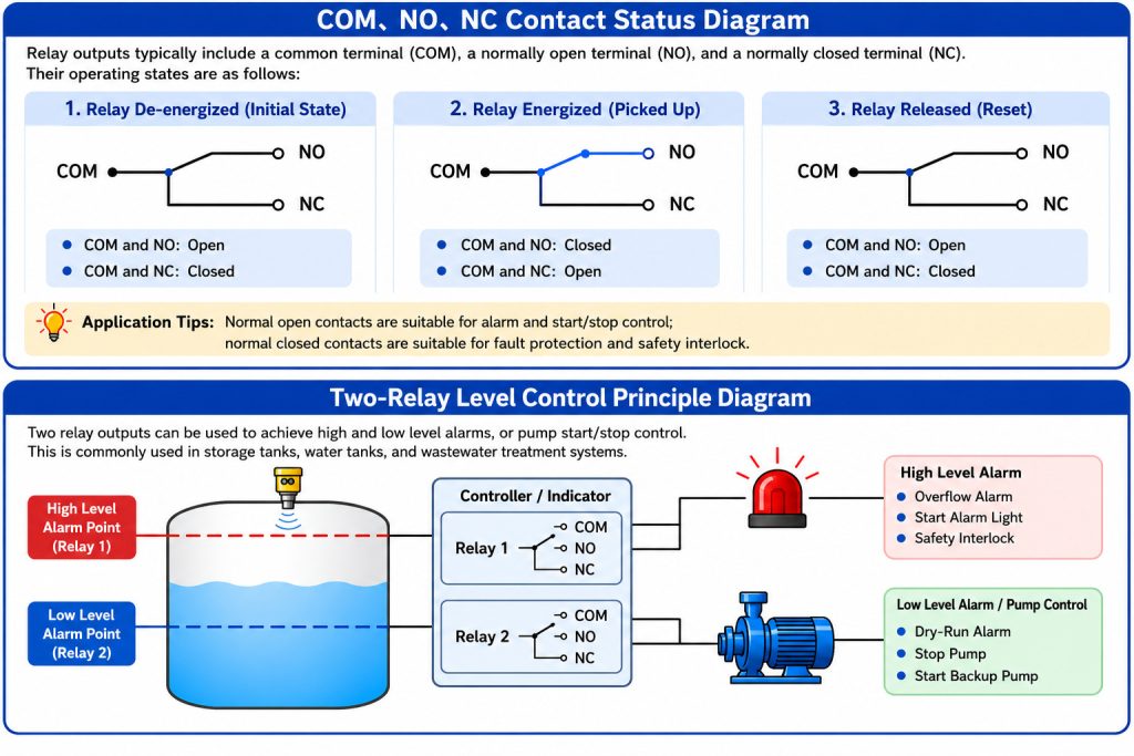
- A common terminal, identified as COM
- A normally open terminal, identified as NO
- A normally closed terminal, identified as NC
In an industrial instrument, the user normally does not control the relay coil directly. Instead, the instrument’s microprocessor controls the relay according to the measured process value and the configured switching point.
For example, when the liquid level inside a storage tank rises above a high-level alarm setting, Relay 1 may activate an alarm lamp. When the level falls below a low-level setting, Relay 2 may stop a pump or generate a low-level warning.
The relay therefore converts a measured process condition into a simple on/off electrical signal.
2. What Does Dual Relay Output Mean?
A dual relay output may also be described as a two-channel relay output or two independent relay outputs.
The word “dual” means that the instrument contains two separate relay channels. Each channel can usually have its own activation value, reset value, delay time and operating logic.
For example:
- Relay 1 can be configured for a high-level alarm
- Relay 2 can be configured for a low-level alarm
The two relays can also be used in other ways:
- Relay 1 controls a filling pump
- Relay 2 controls a drainage pump
Or:
- Relay 1 provides an early warning
- Relay 2 initiates an emergency shutdown
Because each relay can be configured independently, a dual relay output provides more control flexibility than a single relay output.
It is important to understand that two relay outputs do not necessarily operate at the same time. In most instruments, each relay responds to its own programmed condition. However, both relays can activate simultaneously when both switching conditions are satisfied.
3. How Does a Dual Relay Output Work?
A dual relay control process generally includes four stages: measurement, comparison, logic processing and output switching.
Step 1: Measuring the Process Variable
The instrument first measures a process variable through its sensor.
Depending on the type of instrument, this variable may be:
- Liquid level
- Solid material level
- Temperature
- Pressure
- Flow
- Conductivity
- Another industrial process parameter
Step 2: Comparing the Measurement with Setpoints
The user configures an operating condition for each relay.
For example, a level controller may be configured with:
- Relay 1 high-level alarm: 8 metres
- Relay 2 high-high-level alarm: 9 metres
For pump control, it may instead use:
- Pump start level: 2 metres
- Pump stop level: 6 metres
Step 3: Processing the Control Logic
The instrument’s internal controller continuously compares the measured value with the programmed setpoints.
When the activation condition is reached, the controller sends a switching command to the appropriate relay.
Step 4: Switching the Relay Contacts
When the relay is activated, the normally open contact may close and the normally closed contact may open.
This change in contact state completes or interrupts an external control circuit.
The primary purpose of a dual relay output is therefore not to perform the measurement itself. Its purpose is to convert the measurement result into two independent switching signals that can be used by external equipment.
4. What Do COM, NO and NC Mean?
Understanding COM, NO and NC is essential when wiring relay outputs.
COM: Common Terminal
COM stands for “common.”
It is the movable or shared contact of the relay output. In an external circuit, the COM terminal is normally connected to the power source, signal source or common side of the control circuit.
NO: Normally Open Contact
NO stands for “normally open.”
When the relay is not activated, the electrical path between COM and NO is open. Current cannot flow through this contact pair.
When the relay activates, COM and NO become connected.
Normally open contacts are often used when an external device should turn on only after an alarm or control condition occurs.
Typical examples include:
- Turning on an alarm lamp
- Activating a buzzer
- Energising a contactor coil
- Starting a ventilation fan
- Sending an alarm input to a PLC
NC: Normally Closed Contact
NC stands for “normally closed.”
When the relay is not activated, COM and NC are connected. When the relay activates, the connection between COM and NC opens.
Normally closed contacts are commonly used for fault protection, circuit monitoring and fail-safe interlocks.
Because the circuit is closed during normal operation, the control system may detect a relay release caused by an alarm, power failure, broken cable or instrument fault.
Not every instrument provides all three terminals for each relay. Some products provide COM, NO and NC for both relays, while others provide only normally open contacts.
Always check the product wiring diagram before connecting an external circuit.
5. Common Applications of Dual Relay Outputs in Level Control
Dual relay outputs are especially useful in level measurement and level control systems.
5.1 High- and Low-Level Alarms
One of the most common configurations is:
- Relay 1 for a high-level alarm
- Relay 2 for a low-level alarm
When the level exceeds the high-level setpoint, the first relay can activate an overflow alarm.
When the level falls below the low-level setpoint, the second relay can activate an empty-tank or insufficient-material alarm.
This configuration is commonly used in:
- Water tanks
- Storage vessels
- Fuel tanks
- Chemical tanks
- Wastewater wells
- Process containers
- Bulk material silos
5.2 Automatic Pump Start and Stop
Two relay outputs can define separate pump start and stop points.
In a drainage application, for example:
- The pump starts when the liquid reaches the upper setpoint
- The pump stops when the liquid falls to the lower setpoint
This operating method creates a controlled level range and helps prevent the pump from switching on and off too frequently.
Reducing frequent switching can extend the operating life of pumps, contactors and electrical control components.
For a filling application, the logic may be reversed:
- The filling pump starts at the low-level setpoint
- The filling pump stops at the high-level setpoint
5.3 Two-Stage Alarm Control
Dual relay outputs can provide an early alarm and an emergency alarm.
For example:
- Relay 1 activates a high-level warning
- Relay 2 activates a high-high-level shutdown
When the process value approaches a dangerous range, the first relay warns the operator. If the value continues to rise, the second relay may stop a pump, close a valve or activate an emergency interlock.
This two-stage arrangement gives operators more time to respond and improves process safety.
5.4 Filling and Discharge Control
In a process vessel, one relay can control a filling valve while the other controls a discharge pump.
By setting appropriate upper and lower switching points, the instrument can help maintain the material level within a defined operating range.
This reduces the need for manual operation and supports more consistent process control.
5.5 Separate Process and Fault Outputs
One relay may be assigned to a process alarm, while the other is assigned to an instrument fault.
For example:
- Relay 1: high-level alarm
- Relay 2: sensor fault or loss-of-echo alarm
Separating process alarms from device faults allows the control system to determine whether the problem is caused by the process or by the measuring instrument.
6. Dual Relay Output vs. Single Relay Output
A single relay output provides only one independent switching channel. It can normally perform one alarm or control function at a time.
A dual relay output provides two independent channels and can respond to two different process conditions.
For example, a single relay may provide only a high-level alarm. A dual relay output can provide both high- and low-level alarms.
Compared with a single relay, a dual relay output offers several advantages:
- Two independently configurable switching points
- Upper- and lower-limit control
- Pump start and stop control
- Early warning and emergency alarm functions
- Reduced need for additional external controllers
- Greater system integration
- More flexible control logic
However, more relay outputs are not always necessary.
The correct number of relay channels should be selected according to the number of control functions, the complexity of the process and the safety requirements of the application.
7. What Is Relay Hysteresis?
Relay hysteresis is an important setting in level, pressure and temperature control applications.
Suppose a pump start point and stop point are set to exactly the same value. If the measured level fluctuates around that value, the relay may switch repeatedly.
This can cause the pump, contactor or alarm device to turn on and off rapidly.
To prevent this behaviour, the activation point and reset point are separated by a specified amount.
For example:
- High-level relay activation point: 8 metres
- High-level relay reset point: 7.5 metres
The relay activates when the level rises to 8 metres. It does not reset until the level falls to 7.5 metres.
The difference of 0.5 metres is called the hysteresis, deadband or switching differential.
A suitable hysteresis setting improves control stability and reduces mechanical and electrical wear on relay contacts and external equipment.
8. What Is Relay Delay?
Some dual relay instruments allow the user to configure an activation delay or reset delay.
A delay prevents the relay from responding immediately to a short process fluctuation.
For example, waves, foam or turbulence may cause the measured liquid level to briefly exceed an alarm value. Without a delay, the relay could generate a false alarm.
With a five-second activation delay, the alarm condition must remain present for five seconds before the relay switches.
Relay delay is useful for:
- Preventing alarms caused by temporary fluctuations
- Reducing unnecessary pump switching
- Avoiding false control actions
- Stabilising operation in turbulent vessels
- Coordinating several devices in a control sequence
The delay should be selected carefully. A delay that is too long may slow down an important safety response.
9. Can a Dual Relay Output Control a Pump Directly?
This depends on the pump power and the rated capacity of the relay contacts.
The internal relays in most industrial instruments are designed to provide control signals. They are generally not intended to switch large pumps, motors, heaters or other high-current equipment directly.
If the operating voltage or current of the external load exceeds the relay contact rating, the instrument should control an intermediate relay, solid-state relay or contactor.
A common control arrangement is:
Instrument relay output → intermediate relay or contactor coil → pump power circuit
In this arrangement, the instrument switches only the relatively small current required by the contactor coil. The contactor switches the higher current required by the pump motor.
This reduces the risk of:
- Relay contact overheating
- Contact welding
- Electrical arcing
- Instrument damage
- Premature relay failure
When designing the circuit, check the following parameters:
- Maximum contact voltage
- Maximum contact current
- AC or DC load
- Resistive or inductive load
- Continuous operating current
- Starting or inrush current
- Required electrical isolation
Motors, solenoid valves and contactor coils are inductive loads. They can generate high inrush current and voltage transients when switched.
Suitable surge suppression, such as an RC snubber, flyback diode or varistor, may be required.
10. Are Relay Outputs Powered or Unpowered?
Many industrial instruments provide potential-free relay contacts, also known as dry contacts.
A dry contact does not provide its own output voltage. It simply opens or closes an external circuit.
The external circuit must therefore include its own power source.
For example, the relay contact may switch:
- A 24 V DC PLC input
- A 230 V AC alarm lamp circuit
- A contactor coil
- A low-voltage buzzer circuit
Some devices use transistor or powered switching outputs instead of dry relay contacts. These outputs may have polarity and voltage requirements.
Users should never assume that every “switch output” is a potential-free relay output. The product datasheet and terminal diagram should always be checked.
11. How to Select a Dual Relay Output Instrument
When selecting a level meter, controller or alarm unit with dual relay outputs, consider the following factors.
11.1 Define the Control Functions
Determine what each relay must control.
Typical configurations include:
- High- and low-level alarms
- Pump start and stop
- Filling and discharge control
- Warning and emergency shutdown
- Process alarm and instrument fault
- Main pump and backup pump control
11.2 Check the Contact Configuration
Confirm whether each relay provides:
- COM and NO
- COM and NC
- COM, NO and NC
Also check whether the two relays are electrically independent or share a common terminal.
11.3 Check the Contact Rating
The relay contact voltage and current ratings must be suitable for the external circuit.
The rating should not be matched only to the normal operating current. Adequate margin should be allowed for starting current, switching transients and load type.
11.4 Confirm Hysteresis Settings
For level, temperature and pressure control, adjustable hysteresis helps prevent unstable relay switching.
Some instruments allow the user to configure separate activation and reset values. Others use a fixed hysteresis.
11.5 Check the Available Relay Logic
Depending on the instrument, the relays may support:
- High alarm
- Low alarm
- High-high alarm
- Low-low alarm
- Window or range alarm
- Pump filling mode
- Pump drainage mode
- Fault alarm
- Inverted relay logic
- Latching output
Choose a product whose available logic matches the process requirements.
11.6 Consider Fail-Safe Operation
In critical applications, determine what happens when the instrument loses power.
A relay may be configured to remain energised during normal operation and release during an alarm or power failure. This is often called fail-safe or de-energise-to-trip operation.
The correct use of NO and NC contacts depends on the required safe state of the system.
11.7 Check Electrical Isolation
Proper isolation between the relay circuit, power supply and measurement electronics helps reduce interference and improves system reliability.
Isolation is particularly important when the relay switches circuits with different voltages or when the instrument is installed in an electrically noisy environment.
12. Installation and Wiring Precautions
Safe and reliable operation depends on correct wiring and suitable circuit protection.
Important precautions include:
- Disconnect power before wiring
- Follow the manufacturer’s terminal diagram
- Do not exceed the relay contact rating
- Use a contactor for pumps and high-power equipment
- Install surge protection for inductive loads
- Separate signal cables from high-voltage power cables
- Configure suitable hysteresis and delay values
- Use correctly rated fuses or circuit breakers
- Check terminal tightness during routine maintenance
- Have qualified personnel handle mains-voltage circuits
If a relay switches frequently, becomes hot or develops welded contacts, inspect the external load, inrush current and suppression circuit rather than simply replacing the instrument.
13. Common Questions About Dual Relay Outputs
Can Both Relays Activate at the Same Time?
Yes.
If the operating conditions for both channels are satisfied, both relays can remain active at the same time. The exact behaviour depends on the instrument’s configuration and relay logic.
Are the Two Relay Channels Completely Isolated?
Not always.
Some instruments provide two fully independent relay contact groups. Others may use a shared common terminal.
The wiring diagram should be checked before installation.
Does a Relay Output Supply Voltage?
Most industrial relay outputs are dry contacts and do not supply voltage.
An external power source is required for the alarm, PLC input, contactor or other controlled circuit.
However, some products use powered electronic outputs, so the datasheet must be verified.
Can Two Relay Outputs Control Two Pumps?
They can provide control signals for two pumps.
For example, one relay may control the main pump and the other may control a backup pump. The relays can also be used for alternating pump operation, depending on the controller logic.
Large pump motors should normally be switched through separate contactors rather than directly through the instrument relays.
What Is the Difference Between a Relay Output and a 4–20 mA Output?
A relay output is a discrete switching signal. It normally has only two logical states: open or closed.
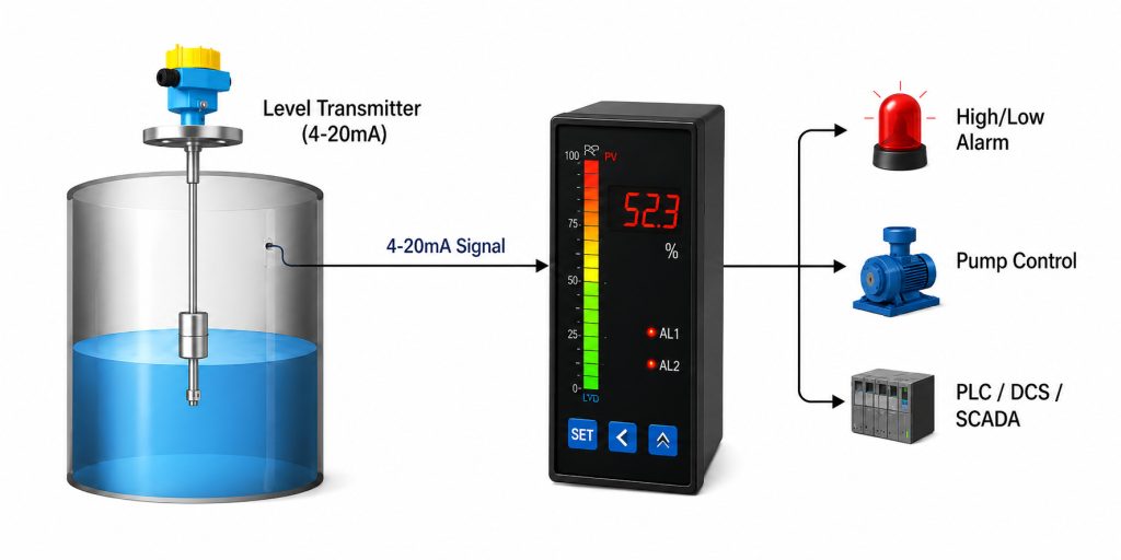
A 4–20 mA output is a continuous analogue signal that represents the real-time measured value.
For example, the 4–20 mA signal may indicate the current liquid level, while the relays provide separate high- and low-level alarms.
What Is the Difference Between a Relay and a Transistor Output?
A mechanical relay provides physical contact isolation and can often switch AC or DC circuits. However, it has a limited mechanical life and a lower switching speed.
A transistor output has no mechanical contacts and can switch quickly, but it usually works only with specified DC voltage and current ranges.
The appropriate output type depends on the load and control system.
14. Conclusion
A dual relay output is a common switching-output configuration used in industrial instruments and automation systems.
It consists of two independently controlled relay channels. Each relay can respond to a separate setpoint or operating condition.
Dual relay outputs can be used for:
- High- and low-level alarms
- Pump start and stop control
- Two-stage warning systems
- Filling and drainage control
- Valve operation
- Equipment interlocks
- Process alarms and instrument fault outputs
Compared with a single relay output, a dual relay arrangement provides greater control flexibility and can reduce the need for additional external control devices.
However, users should consider more than the number of relays. Contact configuration, voltage and current ratings, hysteresis, delay time, relay logic, electrical isolation and fail-safe behaviour are all important selection factors.
For pumps, motors, solenoid valves and other inductive or high-power loads, the instrument relay should normally control an intermediate relay or contactor rather than switching the main load directly.
By selecting the correct relay configuration and following appropriate wiring practices, a dual relay output can provide reliable alarm, pump-control and safety-interlock functions in a wide range of industrial applications.

