
1. What Are Two-Wire and Four-Wire Industrial Instruments?
When selecting radar level meters, ultrasonic level meters, submersible level transmitters, differential pressure level transmitters, and other industrial instruments, the terms “two-wire” and “four-wire” frequently appear in product specifications.
The term “wire system” mainly describes the relationship between the instrument’s power supply wiring and signal transmission wiring.
In simple terms:
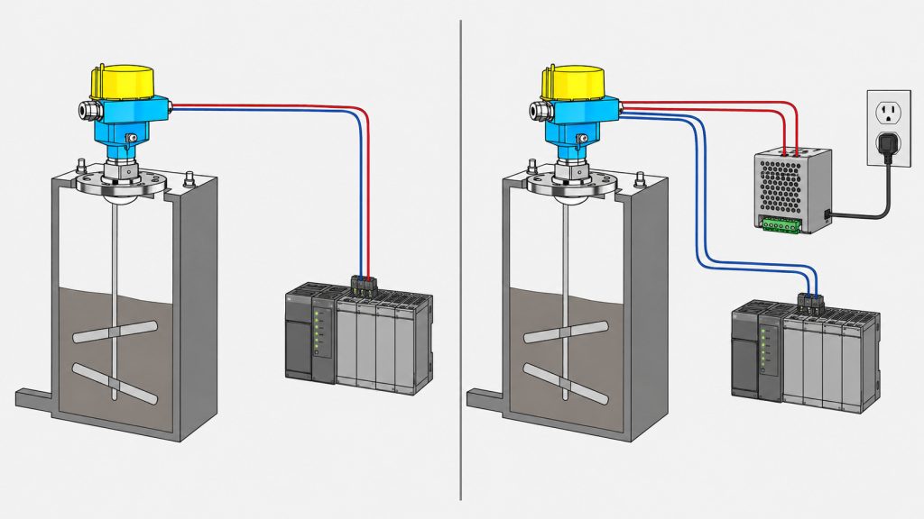
A two-wire level meter uses the same pair of wires for both instrument power and measurement signal transmission.
A four-wire level meter uses two wires to supply power to the instrument and another two wires to transmit the analog output signal independently.
Both configurations may provide a standard 4–20 mA current output. However, they differ significantly in power architecture, energy consumption, load capacity, wiring requirements, installation cost, and suitability for different operating conditions.
For industrial automation systems, understanding the principles of two-wire and four-wire level instruments helps prevent incorrect product selection, wiring failures, unstable signals, insufficient loop voltage, and problems with PLC or DCS signal acquisition.
2. How Does a Two-Wire Level Meter Work?
A two-wire level meter is also known as a loop-powered level transmitter or two-wire level transmitter.
It is typically powered by a 24 V DC supply. The power supply, level transmitter, and PLC analog input module form a single series current loop.
A typical loop connection is:
24 V DC positive terminal → level meter positive terminal → level meter negative terminal → PLC analog input terminal → power supply negative terminal
Within this loop, the level meter adjusts the loop current to represent changes in the measured level.
The most common output range is 4–20 mA:
- 4 mA normally represents the lower range value, such as an empty tank or minimum liquid level.
- 20 mA normally represents the upper range value, such as a full tank or maximum liquid level.
- 12 mA generally represents approximately 50% of the configured measurement range.
For example, if a tank level transmitter is configured for a measuring range of 0–10 meters:
- 4 mA represents 0 meters.
- 12 mA represents approximately 5 meters.
- 20 mA represents 10 meters.
One important feature of a two-wire instrument is that it must continue operating even when the output is at 4 mA.
The transmitter’s internal electronic circuits must use the limited energy available from the current loop to power the sensing element, process the measurement signal, drive the display, and support communication functions.
This limited power availability is the main reason why two-wire level meters are designed as low-power devices.
Key Characteristics of Two-Wire Level Meters
First, the same two wires are used for both power supply and signal transmission, simplifying field wiring.
Second, two-wire instruments are normally powered by a 24 V DC current loop and are well suited for connection to PLCs, distributed control systems, signal isolators, intrinsic safety barriers, and isolation barriers.
Third, the most common output signal is 4–20 mA. Many modern instruments can also superimpose HART digital communication on the analog current signal.
Fourth, two-wire level instruments consume relatively little power, making them suitable for remote installation, long-distance signal transmission, and hazardous-area applications.
Fifth, the loop voltage must be sufficient to overcome the minimum operating voltage of the instrument and all voltage drops caused by the load resistance, signal cables, PLC input module, safety barrier, and other connected devices.
For example, a two-wire radar level meter may require a minimum terminal voltage to operate correctly. The PLC analog input module, intrinsic safety barrier, signal isolator, and long field cables all create voltage drops.
If the total loop supply voltage is insufficient, the level meter may repeatedly restart, show a flashing display, remain at a low current output, lose HART communication, or fail to operate altogether.
3. How Does a Four-Wire Level Meter Work?
A four-wire level meter separates the power supply circuit from the output signal circuit.
Two wires are dedicated to powering the instrument, while the other two wires transmit a 4–20 mA, 0–20 mA, 0–10 V, or other standard process signal.
A typical four-wire connection consists of:
Power supply positive and negative terminals connected to the instrument power input, with the signal output positive and negative terminals connected separately to the PLC or DCS analog input module.
Because power and signal transmission are independent, a four-wire level meter does not need to rely on the limited energy available from a 4–20 mA loop.
It can therefore support higher-power sensors, larger displays, stronger signal processors, heating modules, relays, communication modules, purge systems, and other advanced functions.
The power supply for a four-wire level meter may include:
- 24 V DC
- 220 V AC
- 110 V AC
- Wide-range AC/DC power
- Other manufacturer-specified power supplies
The actual supply voltage must always be verified using the product nameplate, technical manual, and terminal wiring diagram.
The term “four-wire” indicates that the power and signal circuits are separate. It does not indicate a specific voltage level.
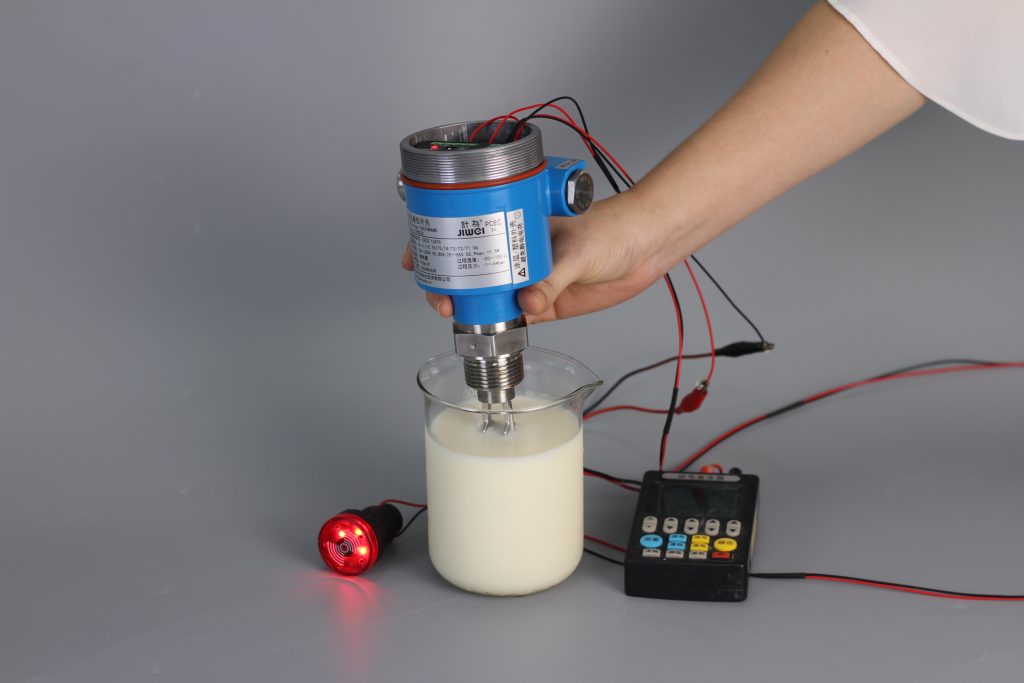
Key Characteristics of Four-Wire Level Meters
First, the independent power supply provides greater available power and supports instruments with higher energy requirements.
Second, the power and output circuits can often be designed with better isolation and greater flexibility.
Third, four-wire instruments are more suitable for additional functions such as local displays, relay alarms, air purging, heating, multiple outputs, and on-site control.
Fourth, more field wiring is required, increasing cable, terminal, installation, and maintenance costs.
Fifth, when an instrument uses an AC power supply, particular attention must be paid to protective grounding, insulation, cable separation, and electrical safety.
4. What Is the Difference Between Two-Wire and Four-Wire Level Meters?
4.1 Number of Wires
A two-wire instrument requires only one pair of wires, which carries both power and the output signal.
A four-wire instrument generally uses two wires for power and two wires for signal transmission.
However, “four-wire” describes the electrical architecture rather than the exact number of terminals on the device.
Some level meters may also include protective earth terminals, relay outputs, RS485 communication terminals, digital inputs, or service connections. Therefore, the actual number of terminals may exceed four.
4.2 Power Supply Method
A two-wire level meter is normally powered by a 24 V DC current loop.
A four-wire level meter uses an independent power source. Depending on the model, this may be 24 V DC, 110 V AC, 220 V AC, or a wide-range AC/DC supply.
4.3 Available Power
The current and power available to a two-wire instrument are limited. Its internal electronics must therefore be designed for low-power operation.
A four-wire instrument has an independent power supply and can support higher-power ultrasonic transducers, radar modules, signal processors, displays, heaters, purge systems, and control functions.
4.4 Wiring and Installation Cost
Two-wire instruments require fewer conductors, cables, junction box terminals, and control cabinet connections.
This can significantly reduce installation costs, particularly when a plant contains a large number of measurement points or when the distance between the field instrument and the control room is long.
Four-wire instruments require more conductors and more complex wiring, resulting in higher material, installation, and maintenance costs.
4.5 Hazardous-Area Applications
Two-wire level meters are commonly used in intrinsically safe systems.
An intrinsic safety barrier or galvanic isolator limits the voltage, current, and electrical energy entering the hazardous area, helping ensure that the circuit cannot ignite a potentially explosive atmosphere under specified fault conditions.
Four-wire level meters can also be used in hazardous areas. However, the design must match the instrument’s explosion-protection method, supply voltage, certification, and installation requirements.
For example, a four-wire explosion-proof radar level meter must be installed according to flameproof or explosion-proof wiring requirements. It cannot automatically be treated as a two-wire intrinsically safe device.
4.6 Functional Expansion
Four-wire level meters generally have greater flexibility for integrating relay outputs, local control, heating, alarms, multiple analog outputs, and communication interfaces.
Two-wire instruments can also provide advanced diagnostics and digital communication, but their overall functionality remains constrained by the power available from the current loop.
5. Which Wiring System Is Used by Common Level Instruments?
Radar Level Meters
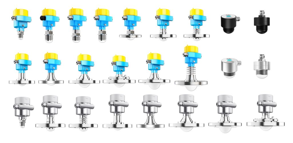
Radar level meters are available in both two-wire and four-wire versions.
Two-wire radar level meters are widely used for storage tanks, chemical vessels, water treatment basins, oil tanks, silos, and bulk solid applications.
Their main advantages include simple wiring, 4–20 mA output, HART compatibility, low power consumption, and suitability for intrinsic safety applications.
Four-wire radar level meters are often selected for difficult measurement conditions, long measuring ranges, high-performance signal processing, AC-powered installations, or applications requiring additional functions.
A four-wire radar level meter is not automatically more accurate than a two-wire model.
Measurement accuracy also depends on factors such as radar frequency, antenna design, signal processing algorithm, installation position, process connection, vessel geometry, dielectric constant, false echoes, foam, dust, and vapor.
Ultrasonic Level Meters
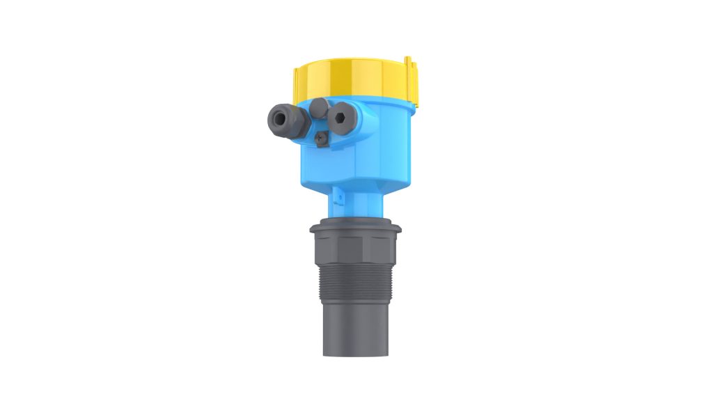
Integrated ultrasonic level meters are commonly available in both two-wire and four-wire configurations.
Low-power products with shorter measuring ranges can use a two-wire 4–20 mA loop-powered design.
When the device requires higher transmission power, relay outputs, an AC power supply, local control, or multiple output interfaces, a four-wire configuration is more common.
A split-type ultrasonic level measurement system may use a dedicated cable between the sensor and the controller.
Therefore, the number of wires connected to the ultrasonic sensor alone does not necessarily determine whether the complete system is two-wire or four-wire.
Submersible Level Transmitters
Most submersible hydrostatic level transmitters use a two-wire 4–20 mA output.
The sensing element is connected to the power supply and control system through a special vented cable. These instruments are widely used in water tanks, wells, reservoirs, wastewater systems, pumping stations, and open channels.
Some models may also provide three-wire voltage outputs, RS485 communication, or other power and signal configurations.
Differential Pressure Level Transmitters
Industrial differential pressure transmitters commonly use a two-wire 4–20 mA output with HART communication.
They are widely applied to level measurement in closed vessels, pressurized tanks, steam drums, chemical process columns, and other pressure-containing equipment.
Magnetic Level Gauge Transmitters
A basic magnetic level gauge is a mechanical instrument that provides local visual indication.
When a remote transmitter is added, the most common output is a two-wire 4–20 mA signal.
If the magnetic level gauge is also equipped with level switches, high- and low-level alarms, a local controller, or a separate display unit, multiple terminal groups may be present. Each group must be identified according to its specific electrical function.
6. How to Wire a Two-Wire Level Meter Correctly
A two-wire 4–20 mA level meter normally has a positive terminal and a negative terminal.
Before wiring the instrument, determine whether the PLC analog input module is active or passive.
Passive Analog Input
A passive analog input module does not provide power to the field loop.
An external 24 V DC supply is therefore required. The power supply, level meter, and PLC input channel must be connected in series.
A common connection is:
24 V DC positive → transmitter positive → transmitter negative → PLC analog input positive → PLC analog input negative → 24 V DC negative
The exact connection may vary depending on the PLC module design, so the module wiring diagram must always be checked.
Active Analog Input
An active analog input module provides loop power to a two-wire transmitter.
In this case, an additional external power supply is normally unnecessary.
Connecting another power source to an already powered loop may create a voltage conflict, cause incorrect measurements, trip protection devices, or damage the instrument and input module.
The PLC or DCS manual should therefore be checked to determine whether the analog input channel includes transmitter power.
Two-Wire Wiring Precautions
Always observe the correct polarity.
Calculate the total loop load and verify that the voltage remaining at the instrument terminals exceeds the specified minimum operating voltage.
Shielded cable is generally grounded at one end to reduce ground-loop currents. However, the final grounding method should follow the instrument manufacturer’s instructions and the plant grounding design.
An intrinsically safe circuit must use a correctly matched safety barrier or galvanic isolator.
The entity parameters or electrical safety parameters of the field instrument, barrier, cable, and associated apparatus must be compatible.
HART communication normally requires an appropriate loop resistance. If the loop resistance is too low, a HART handheld communicator or configuration modem may not communicate correctly.
7. How to Wire a Four-Wire Level Meter Correctly
For a four-wire level meter, the power terminals and signal terminals must first be identified separately.
Common terminal markings include:
- L and N: AC power input
- PE: Protective earth
- 24V+ and 0V: DC power input
- I+ and I−: 4–20 mA current output
- V+ and V−: Voltage output
- COM, NO, and NC: Relay common, normally open, and normally closed contacts
One of the most important wiring precautions is to prevent AC mains voltage from being connected to the 4–20 mA output terminals.
The analog output terminals must also never be connected to a high-voltage circuit.
If a four-wire level meter has an active 4–20 mA output, the instrument actively drives the output current. The PLC input must therefore be configured to receive an active current signal.
If the output is passive, externally powered, or isolated but loop-powered, an additional loop supply may be required.
The wiring cannot be determined from the term “four-wire” alone. The manufacturer’s terminal diagram and output specifications must always be consulted.
8. How to Choose Between a Two-Wire and Four-Wire Level Meter
For most conventional storage tanks, water tanks, silos, process vessels, and open basins, a two-wire level meter is usually the more economical choice when only a 4–20 mA or HART signal is required.
A two-wire level meter is generally suitable when:
- The installation contains many measurement points.
- The distance between the instrument and the control room is long.
- A PLC or DCS receives the 4–20 mA signal.
- Intrinsic safety is required.
- Reducing cable and installation costs is important.
- AC power is not readily available at the measurement point.
- Low power consumption is preferred.
- The device does not require high-power accessories.
A four-wire level meter may be more appropriate when:
- The instrument requires greater transmission or processing power.
- Relay alarms or local control functions are needed.
- Heating, purging, or other auxiliary functions are required.
- A stable independent power supply is already available.
- The instrument must provide multiple output signals.
- The system uses a split-type design.
- A large display or advanced communication module is required.
- The application involves complex measurement electronics.
The wiring system should never be the only selection criterion.
Level meter selection should also consider:
- Measuring range
- Process temperature
- Process pressure
- Dielectric constant
- Medium density
- Foam
- Vapor
- Condensation
- Dust
- Agitation
- Inlet flow
- Internal tank structures
- Nozzle dimensions
- Blocking distance
- Antenna type
- Process connection
- Enclosure protection rating
- Corrosion resistance
- Hazardous-area classification
- Explosion-protection certification
A correctly selected two-wire instrument can perform better than an incorrectly selected four-wire instrument, and vice versa.
9. Common Faults and Troubleshooting Methods
No Current Output from a Two-Wire Level Meter
First, check whether the 24 V DC supply is operating correctly.
Then check whether:
- The polarity has been reversed.
- The loop is open.
- A terminal is loose.
- The PLC analog input is wired correctly.
- The analog input channel is configured for current rather than voltage.
- A fuse or protection device has operated.
- The safety barrier is compatible and powered.
The actual voltage at the instrument terminals should also be measured while the loop is connected.
A power supply may show 24 V when unloaded, but the voltage at the transmitter may fall below the minimum operating requirement after the safety barrier, PLC input resistance, and long signal cable are included.
Output Remains Near 4 mA
The actual level may be at the lower range value, but a current near 4 mA can also indicate:
- No valid echo has been detected.
- The instrument range is configured incorrectly.
- The measured level is outside the configured range.
- The sensor is blocked or contaminated.
- The instrument is in a startup state.
- The output is in a fault or alarm mode.
- The PLC scaling does not match the transmitter range.
Some instruments use a current below 4 mA or above 20 mA to indicate a fault condition. The exact alarm current depends on the instrument configuration and the applicable signal standard.
Four-Wire Level Meter Has a Display but No PLC Signal
This usually means the instrument power supply is functioning, but the output signal circuit has a problem.
Check:
- The I+ and I− terminals
- PLC analog input wiring
- Active or passive signal compatibility
- Common terminal connections
- Signal isolation
- Analog input channel configuration
- Output range settings
- Whether the transmitter is configured for current or voltage output
Unstable or Fluctuating Level Signal
Signal fluctuation is not necessarily caused by the two-wire or four-wire configuration.
Possible causes include:
- Agitation inside the tank
- Turbulence
- Rapid filling or emptying
- Foam
- Dust
- Vapor
- Condensation
- False echoes
- Poor grounding
- Electromagnetic interference
- Unstable power supply
- Incorrect installation position
- Excessively long or narrow mounting nozzles
- Nearby tank walls, ladders, pipes, or internal structures
The process conditions and installation geometry should be evaluated before concluding that the wiring system is responsible.
10. Frequently Asked Questions About Two-Wire and Four-Wire Level Meters
How Can a Two-Wire Level Meter Receive Power Through Only Two Wires?
The two wires form a complete series current loop.
The instrument draws operating power from the loop while simultaneously regulating the loop current to transmit the measured level.
Is Every Two-Wire Level Meter a 4–20 mA Device?
No.
However, two-wire 4–20 mA is the most common configuration in industrial process measurement.
Some instruments also support HART communication superimposed on the 4–20 mA analog signal.
Does Every Four-Wire Level Meter Use 220 V AC?
No.
“Four-wire” only means that the power supply and output signal use separate conductors.
The instrument may use 220 V AC, 110 V AC, 24 V DC, or another specified power source.
Which Is More Accurate: Two-Wire or Four-Wire?
The wiring configuration does not directly determine measurement accuracy.
Accuracy depends primarily on the measurement principle, sensor quality, instrument electronics, signal processing, calibration, installation, vessel structure, and process conditions.
Can a Two-Wire Level Meter Be Tested with a Standard Multimeter?
Yes. A multimeter set to the DC current range can be connected in series with the loop to measure the output current.
However, the current input of the multimeter must never be connected directly across the power supply.
Doing so may create a short circuit, blow the multimeter fuse, trip the power supply, or damage connected equipment.
Why Does the PLC Display the Wrong Level Even Though the Output Is 4–20 mA?
Common causes include:
- Incorrect PLC scaling
- Mismatched lower and upper range values
- Incorrect analog input type
- Reversed wiring polarity
- Incorrect transmitter range configuration
- Incorrect engineering units
- Active and passive input mismatch
- Excessive loop resistance
- Electrical interference
- Fault current being interpreted as a valid measurement
For example, if the level meter is configured for 0–10 meters but the PLC is scaled for 0–20 meters, the PLC display will be incorrect even though the current signal itself is normal.
11. Conclusion
Two-wire and four-wire systems are the most common electrical configurations used in industrial level measurement.
A two-wire level meter uses the same pair of conductors for both power supply and 4–20 mA signal transmission.
Its main advantages include simple wiring, lower installation cost, suitability for long-distance transmission, low power consumption, and compatibility with intrinsically safe systems.
A four-wire level meter separates the power supply from the output signal.
It offers greater available power and is better suited for high-power measurement electronics, AC-powered installations, multiple outputs, relay control, local displays, heating, purging, and other advanced functions.
When selecting a radar level meter, ultrasonic level meter, submersible level transmitter, differential pressure transmitter, or magnetic level gauge transmitter, the wiring system should be chosen according to:
- The PLC or DCS input type
- Available field power
- Hazardous-area requirements
- Measurement conditions
- Required outputs
- Communication requirements
- Functional requirements
- Installation and maintenance costs
Regardless of whether a two-wire or four-wire level meter is selected, always verify the instrument nameplate, supply voltage, signal type, terminal definitions, output characteristics, and manufacturer’s wiring diagram before installation.
Correct power supply and wiring are essential not only for basic instrument operation, but also for signal stability, electrical safety, measurement reliability, and long-term plant performance.

