
In industrial plants, operators sometimes encounter a situation that seems contradictory:
Two level instruments are measuring the same silo at the same time. One indicates 68%, while the other shows 74%. After inspection, however, both instruments appear to be operating normally.
So which reading is correct?
The answer may be surprising:
Both can be correct.
For liquids such as water or oil, the surface is usually close to horizontal when the liquid is at rest. As a result, a single height can often represent the liquid level throughout the vessel.
Bulk solids are very different.
Materials such as cement, fly ash, lime powder, alumina powder, coal, mineral powder, grain, plastic pellets, and coke do not normally form a flat surface inside a silo. Instead, they create slopes, peaks, valleys, and irregular surfaces that continuously change during filling and discharge.
This means that a single silo can have several different—and equally valid—material levels at the same time.
Understanding this concept is essential when selecting and applying radar level transmitters, vibrating rod level switches, rotary paddle level switches, RF admittance level switches, and other level measurement instruments.
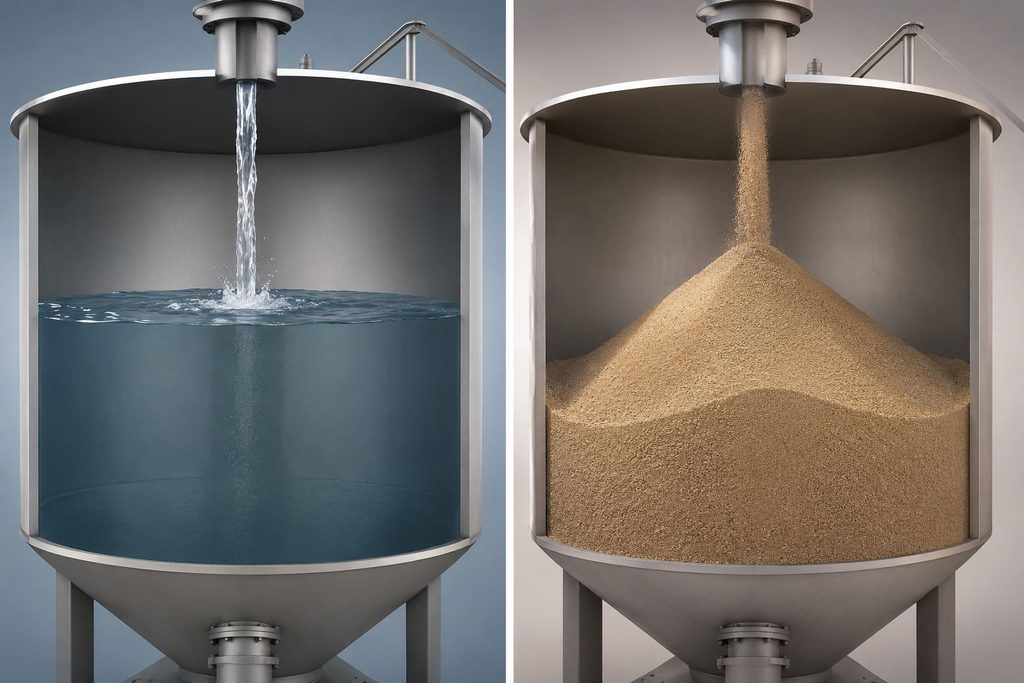
1. Why Does a Liquid Usually Have One Level While Bulk Solids Can Have Many?
Imagine pouring water into a cylindrical tank.
Once the water settles, measuring the surface near the left wall, at the center, or near the right wall will normally produce almost the same result.
Now imagine filling the same vessel with dry sand.
The sand does not automatically form a horizontal surface. Instead, it piles up around the filling point and forms a cone-like mound. The material level near the filling point may be much higher than the level near the silo wall.
This is a typical characteristic of bulk solids.
Powders and granular materials have an angle of repose, sometimes also referred to as a piling or heap angle. When material enters a silo, its surface profile is influenced by many factors, including:
- Particle size and shape
- Material flowability
- Moisture content
- Friction characteristics
- Filling position
- Filling rate
- Silo geometry
- Discharge arrangement
As a result, the material surface can become significantly inclined or irregular.
For example, the material height at the center of a silo may be 8.2 meters, while another point may measure 7.6 meters and a third location only 7.1 meters.
If three instruments measure these three locations and all are operating correctly, then 8.2 m, 7.6 m, and 7.1 m can all be accurate readings.
The instruments are not necessarily disagreeing with each other.
They are simply measuring different points on the same three-dimensional material surface.
This leads to one of the most important principles in bulk solid level measurement:
A level instrument primarily measures the material surface within its measurement path. That reading does not automatically represent a single average level for the entire silo.
2. Filling Creates Peaks, While Discharging Can Create Valleys
The material surface inside a silo is not static.
More importantly, filling and discharging can create almost opposite surface profiles.
During Filling: A Material Peak May Form
Consider a silo with a filling inlet near the center of the roof.
As powder or granules fall into the silo, material accumulates below the filling point and then moves outward along the slope of the pile.
The result may be a cone-shaped surface that is higher in the center and lower toward the walls.
If a radar level transmitter measures close to this peak, it may indicate a significantly higher level than the average filling condition of the silo.
This does not necessarily mean the radar is inaccurate.
The material within that particular measurement area has actually reached that height.
During Discharge: A Material Valley May Form
When material is discharged from the bottom of a silo, the opposite effect can occur.
Material near the outlet begins moving downward first. Material above it flows toward the discharge zone, potentially creating a funnel-shaped depression.
If the level instrument measures near the center of this depression, its reading may be considerably lower than the material level closer to the silo wall.
The same silo can therefore have:
a center-high, edge-low profile during filling, and a center-low, edge-high profile during discharge.
The situation becomes even more complex with eccentric filling, eccentric discharge, multiple inlets, multiple outlets, internal flow structures, or materials with poor flowability.
The surface may develop offset peaks, asymmetric slopes, valleys, localized buildup, or partial collapse.
At that point, asking, “What is the true level of this silo?” becomes more complicated than simply looking for one height value.
3. What Does a Radar Level Transmitter Actually Measure?
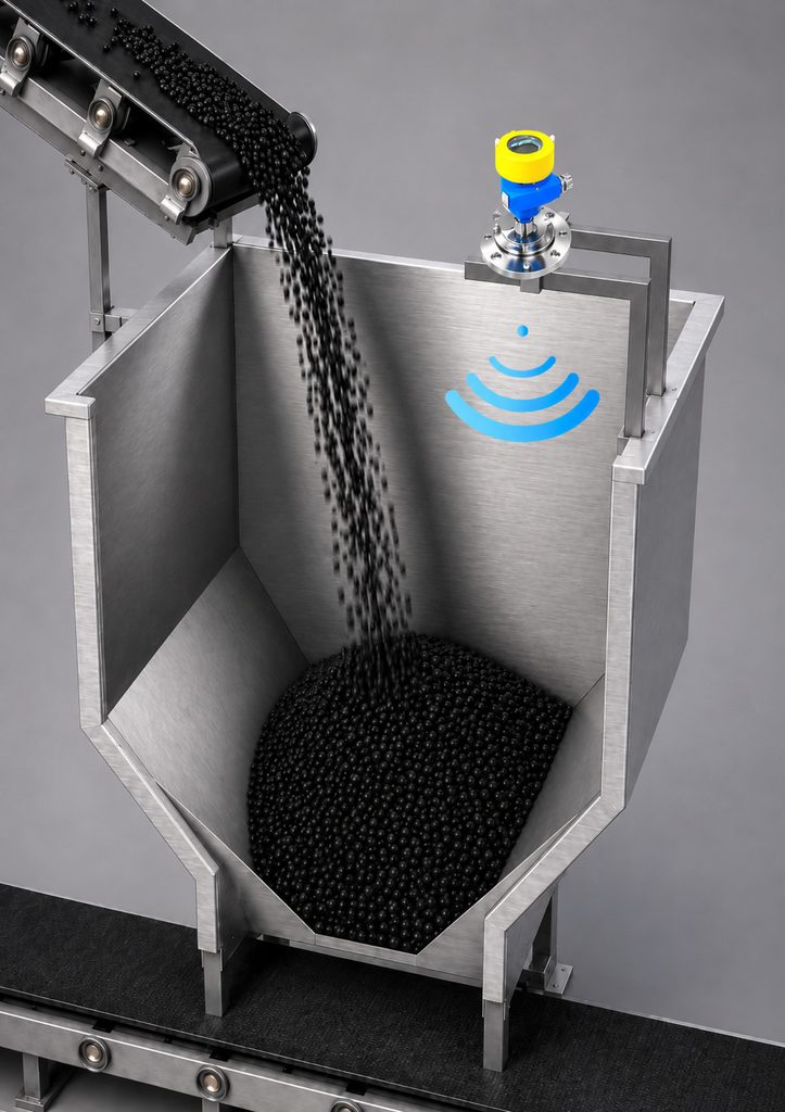
A radar level transmitter is typically installed at the top of a silo. It transmits electromagnetic waves toward the material surface and receives the reflected signal.
By analyzing the returned echo, the instrument calculates the distance between the sensor and the material surface. With the configured silo dimensions and reference points, this distance can then be converted into material height, percentage level, or another process value.
Modern 80 GHz FMCW radar level sensors, for example, use high-frequency millimeter waves and relatively narrow beam angles.
A narrow radar beam can be particularly useful in complex silos because it helps reduce interference from silo walls, support structures, reinforcement beams, ladders, pipes, and other internal obstacles.
However, the narrow beam also highlights an important fact:
The more focused the radar beam is, the more localized the measured material surface can become.
Imagine a large silo with a diameter of 10 meters.
A radar sensor installed away from the center primarily observes the material surface within its beam coverage. It does not automatically scan the entire silo and reconstruct the complete three-dimensional volume of the stored material.
Therefore, when a radar level transmitter displays “72%,” a more technically accurate interpretation is:
Under the current installation position, measurement direction, configured range, and material surface conditions, the detected surface corresponds to approximately 72% level.
That is not exactly the same statement as:
“The silo contains precisely 72% of its total storage capacity.”
The distinction is important, especially in large bulk solid silos.
4. Why Can Changing the Installation Position Change the Reading?
For bulk solid applications, the installation position is effectively part of the measurement system.
Consider two radar level transmitters installed on the roof of the same cylindrical silo.
Sensor A is positioned closer to the center, while Sensor B is installed farther away along the silo radius.
During filling, the material forms a clear cone-shaped pile. Sensor A measures close to the peak, while Sensor B measures the sloping section of the material surface.
Sensor A may indicate 80%, while Sensor B shows 72%.
Both readings can be correct.
If Sensor B were moved to another location, its reading might become 75%.
For this reason, evaluating a level transmitter simply by asking, “Why doesn’t it show the same value as the other instrument?” can be misleading.
A better analysis should consider several questions:
Where is the instrument installed? Where is its beam directed? Where is the filling inlet? Where is the discharge outlet? Are there beams, ladders, reinforcement structures, or dust extraction pipes inside the silo? Is the silo currently being filled or discharged? What is the likely shape of the material surface?
Only when these factors are considered together does the level reading have its full engineering meaning.
5. There Are at Least Four Different Meanings of a “Correct Level”
Once we understand that bulk solids create three-dimensional surfaces, it becomes clear that the term “material level” can refer to several different measurements.
Local Material Level
This is the actual material height at a specific measurement location.
Radar level transmitters, electromechanical plumb bob level sensors, and similar continuous level instruments often provide this type of information under specific installation conditions.
It answers the question:
“How high is the material at this location?”
Average Material Level
An average level represents an equivalent height derived from the overall irregular material surface.
It answers a different question:
“Approximately how full is the silo as a whole?”
When a silo has significant asymmetric buildup, peaks, or valleys, however, a single measurement point cannot automatically provide a true average level.
Inventory-Equivalent Level
For inventory management, the ultimate objective is often not height at all.
What the plant really wants to know is volume or mass.
In this case, the measured level must be combined with silo geometry, hopper dimensions, material surface assumptions, and sometimes bulk density to estimate the amount of stored material.
This leads to another important principle:
Accurate level measurement does not automatically guarantee equally accurate inventory calculation.
Bulk density can vary with material batch, moisture content, aeration, compaction, and storage conditions.
Two silos with exactly the same material volume may therefore contain different material masses.
Control Level
Industrial automation also uses another type of “level” that does not attempt to describe the entire material surface.
Instead, it answers a simple but critical question:
“Has the material reached this specific point?”
This is the role of point level switches such as vibrating rod level switches, rotary paddle level switches, and RF admittance level switches.
A high-level switch may be installed near the upper section of the silo, with an independent high-high level switch positioned above it for overfill protection.
Low-level and low-low level switches can similarly be installed near the bottom.
These devices do not need to tell the control system that the silo is “73.6% full.”
They simply need to determine reliably whether material is present at a predefined position.
From this perspective, a single silo can simultaneously have continuous level measurement, high-level detection, high-high level protection, low-level detection, and low-low level protection.
All are valid “levels,” but each serves a different engineering purpose.
6. If One Measurement Point Cannot Represent the Entire Silo, Why Use Radar?
Because industrial level measurement does not always require a complete three-dimensional reconstruction of the material inside a silo.
What is often needed is stable, repeatable, continuous information that supports process control and operational decisions.
When a radar level transmitter is installed correctly, it can continuously track changes within a representative measurement area.
For example:
At 8:00 a.m., the level is 45%.
At 10:00 a.m., it reaches 57%.
At noon, it reaches 69%.
The 69% reading does not mean that every point across the irregular material surface is exactly at 69% of the silo height.
But the trend clearly shows that the silo is being filled.
This information can help the control system and operators understand the filling process, estimate how quickly the material level is rising, anticipate when the silo may approach its upper operating limit, and adjust conveying operations accordingly.
In many applications, therefore, the value of continuous level measurement is not limited to one instantaneous number.
The trend is equally important.
Does the reading rise during filling? Does it decrease during discharge? Is the change continuous and consistent with the process? Are there unexpected jumps or periods when the measurement becomes stationary?
These questions are central to effective radar level measurement.
7. Why Combine Continuous Level Measurement with Point Level Detection?
If continuous radar measurement represents a localized surface condition, should critical overfill protection rely entirely on the percentage displayed by the radar?
For important silo applications, a more robust approach is often to assign different functions to different instruments.
A radar level transmitter can provide continuous measurement to the PLC, DCS, or plant operator.
A vibrating rod, rotary paddle, or RF admittance level switch can independently detect a predefined high or low level.
For example, as a radar transmitter indicates that the level is approaching 85%, operators know that the silo is moving toward its high-level region.
When material physically reaches an independently installed high-level switch, the switch changes state and can trigger an alarm or stop the filling equipment.
These two signals do not mean exactly the same thing.
The continuous transmitter answers:
“Approximately where is the material surface, and how is it changing?”
The point level switch answers:
“Has material physically reached this critical position?”
When used together, the two measurement methods can complement each other.
If the continuous reading and the point level status become significantly inconsistent, the discrepancy can also alert operators to possible uneven filling, material buildup, an unusual peak, parameter changes, or an instrument-related problem.
Continuous level transmitters and point level switches are therefore not necessarily redundant devices. They can perform different functions within the same measurement and protection strategy.
8. How Can Material Level Measurement Become More Representative?
For irregular bulk solid surfaces, the goal should not be to force the silo to have one theoretically “perfect” level value.
The more practical objective is to make the measurement appropriate for its intended purpose.
First, understand the material.
Powders, granules, and coarse bulk solids behave differently. Particle size, moisture, dielectric properties, flowability, and angle of repose can all influence both the material surface and measurement performance.
Second, understand how the silo is filled and discharged.
Is filling centered or eccentric? Is there one inlet or several? Is material discharged from the center or from an offset outlet?
These factors strongly influence where peaks and valleys form.
Third, select the radar installation position carefully.
The sensor should generally avoid direct filling streams and obvious internal obstructions. The silo diameter, height, filling direction, expected material surface, beam direction, and potential false echoes should all be considered during installation and commissioning.
Fourth, define the actual measurement objective.
If the purpose is simply to monitor process trends, one representative continuous measurement point may be sufficient.
If the objective is overfill prevention, independent point level detection may deserve greater attention.
If the plant requires highly accurate inventory calculations, multiple measurement points, three-dimensional surface information, silo geometry, and bulk density data may be necessary.
Different measurement objectives require different definitions of “correct.”
9. When Do Different Readings Actually Indicate a Problem?
When two level instruments show different values, one of them should not automatically be considered faulty.
The first question is whether the difference can reasonably be explained by the material surface.
If Sensor A is measuring a peak while Sensor B is measuring a slope, a difference in level is expected.
If both measurements change consistently during filling and discharge, the instruments may both be working exactly as intended.
Further investigation becomes necessary when the behavior cannot be explained by the process.
Typical warning signs include:
- A level reading remains fixed even during significant filling or discharge.
- The measured value suddenly jumps without a corresponding process change.
- The indicated level rises continuously while the silo is being discharged.
- The radar consistently locks onto a fixed internal structure.
- The measurement beam is directly affected by the filling stream.
- Continuous level readings and independent point level switches remain inconsistent for reasons that cannot be explained by the material surface.
In these situations, the installation position, echo signal, configuration parameters, material buildup, process conditions, and instrument status should be checked systematically.
This approach is usually more useful than simply comparing two numbers and deciding that the instrument with the different reading must be wrong.
10. Professional Level Measurement Is Not About Making Every Instrument Show the Same Number
It is tempting to assume that if several instruments are installed on the same silo, the closer their readings are, the more accurate the measurement must be.
For liquids, this assumption can sometimes be reasonable.
For bulk solids, it can be misleading.
A large powder or granular material silo may contain peaks, valleys, slopes, localized buildup, and uneven collapse at the same time.
Instruments installed at different positions may therefore be observing genuinely different parts of the material surface.
Two different readings do not necessarily contradict each other.
The more important questions are:
Is each instrument accurately measuring the area it is intended to measure? And can these measurements together support inventory monitoring, process control, and safety protection?
Once level measurement is viewed from this perspective, an important fact becomes clear:
The same silo can have multiple “correct” material levels at the same time.
A radar level transmitter observes a continuously changing material surface within its measurement area.
A point level switch monitors whether material has reached a critical position.
An inventory management system may be concerned with something different again: the estimated volume or actual mass of material stored throughout the silo.
All of these values are related to “level,” but they answer different questions.
The real objective of industrial level measurement is therefore not to find one universal number that describes every possible condition.
It is to determine what information the process actually needs from that number.
Only after the measurement objective is clearly defined can material properties, silo geometry, filling and discharge behavior, measurement technology, and instrument installation be properly combined.
That is how multiple “correct levels” become useful, reliable process information.

