
Introduction
Wood chips are one of the most important raw materials in chemical and mechanical pulping.
Before entering the pulping process, logs are normally debarked, chipped, screened, transported, and temporarily stored. Depending on the mill layout, wood chips may be held in large silos, chip bins, bunkers, or other storage vessels before being transferred to digesters or downstream preparation systems.
At first glance, wood chip silo level measurement may appear simpler than measuring pulp slurry or corrosive process liquids.
In reality, bulk-solid measurement introduces an entirely different set of challenges.
Wood chips do not form a flat surface like water. During filling, the material may create a high pile under the inlet. During discharge, a depression or funnel can form above the outlet. Bridges may develop and later collapse. Dust can fill the headspace, and tall storage silos can require measurement over considerable distances.
As a result, a level instrument must do more than simply detect the nearest object inside the silo.
It must reliably identify the useful wood-chip surface despite continuously changing material geometry.
For these applications, modern 80 GHz radar level meters are increasingly attractive because they combine non-contact measurement, a narrow focused beam, long measuring capability, and signal processing designed for difficult bulk-solid surfaces.
This article explains the main challenges of wood chip level measurement, why high-frequency radar is well suited to the application, and how to install a radar level meter correctly in a pulp mill chip silo.

Wood Chip Handling Before Pulping
Wood preparation is one of the first major stages in pulp production.
After logs arrive at the mill, they may pass through processes such as:
- Debarking
- Chipping
- Chip screening
- Oversize-chip handling
- Fines separation
- Conveying
- Chip storage
- Metering to the pulping process
Storage provides an important buffer between wood preparation and downstream production.
The chipper and incoming wood-handling system do not always operate at exactly the same rate as the digester or pulping process. A storage silo or chip bin therefore allows the mill to maintain a more stable supply of chips.
Reliable inventory information helps operators understand how much material is available and whether downstream processes can continue operating.
This makes continuous level measurement an important part of wood-chip handling automation.
Where Is Wood Chip Level Measurement Used?
Depending on the mill design, level instruments may be installed on:
- Wood chip silos
- Chip bins
- Day bins
- Surge bins
- Chip bunkers
- Intermediate storage vessels
- Reclaim bins
- Conveyor transfer bins
Some vessels are relatively small buffers.
Others are tall storage silos with large diameters and long measuring distances.
The same measurement principle may be useful in several locations, but the radar configuration and installation position should always be selected according to the actual vessel.
Why Is Wood Chip Silo Level Measurement Difficult?
A wood chip silo is fundamentally different from a liquid tank.
The sensor is not looking at a flat horizontal surface.
Instead, it is looking at a changing three-dimensional pile of irregular bulk material.
Several conditions must therefore be considered.
1. Uneven Material Surface
Wood chips vary in size, shape, moisture content, and orientation.
When chips fall into a silo, they accumulate naturally rather than spreading immediately into a perfectly horizontal surface.
The result may include:
- Sloped surfaces
- Peaks
- Valleys
- Filling cones
- Local depressions
- Irregular piles
A continuous level instrument measures a specific point or area of this uneven surface.
This means that the measured distance depends partly on where the sensor is aimed.
For this reason, installation position is especially important in bulk-solid level measurement.
2. Angle of Repose
Bulk solids naturally form a slope.
This slope is commonly associated with the material’s angle of repose.
Wood chips falling from a conveyor or chute often create a pile whose highest point is relatively close to the filling location.
The pile then slopes downward toward other areas of the silo.
A radar mounted directly above one part of the vessel may therefore measure a significantly different surface height from a radar aimed at another area.
This does not necessarily mean that either measurement is incorrect.
It means that engineers need to decide what the level value is intended to represent.
For example:
- Maximum pile height
- Average operational level
- Material level near the discharge zone
- Inventory trend
- High-level protection
The intended measurement objective should be defined before choosing the final sensor position.
3. Filling Peaks
When chips enter the silo from a conveyor or chute, a high material peak can form below or near the filling point.
The peak may move as filling conditions change.
Installing a level sensor directly above the inlet can create several problems.
First, the radar may measure the falling material stream rather than the stored material surface.
Second, the sensor may be exposed to stronger dust.
Third, the pile directly beneath the inlet may not represent the average amount of material in the silo.
For these reasons, positioning the radar directly above the filling stream is normally avoided when another suitable mounting location is available.
4. Discharge Cones and Rat-Holing
The material surface also changes during emptying.
As chips are withdrawn from the bottom of the silo, a depression can form over the discharge point.
In some bulk-solid systems, material near the center flows more freely while material near the walls remains relatively stationary.
This can produce a funnel-shaped discharge pattern or a channel sometimes described as rat-holing.
The level measured at one point may therefore change more rapidly than the average inventory in the entire vessel.
This is an important distinction.
A level transmitter normally provides distance to the material surface at the measuring location. It does not directly create a complete three-dimensional map of the entire chip pile.
5. Material Bridging
Wood chips can also form bridges.
Instead of flowing evenly toward the outlet, chips may temporarily support one another across part of the vessel.
This can leave an empty space below material that still appears relatively high from above.
The bridge may later collapse suddenly.
For a conventional top-mounted level transmitter, this creates an important limitation.
The instrument reports the surface it can see.
It cannot automatically determine whether a hidden void exists underneath that surface.
Therefore, level measurement should not be treated as a substitute for proper silo-flow design or blockage detection.
This distinction improves both measurement reliability and plant safety.
6. Dust During Filling
Dry wood chips can generate substantial dust when transferred by conveyors, chutes, and other handling equipment.
During active filling, the space between the sensor and the material surface may contain airborne particles.
Dust is one of the reasons radar is frequently considered for bulk-solid silos.
Radar uses electromagnetic waves rather than acoustic waves.
A correctly selected industrial radar can often maintain a useful signal through dusty headspace conditions that would make some other measurement principles more difficult.
However, the statement should not be exaggerated.
Extremely heavy deposits directly on the antenna can still reduce measurement performance.
The mounting location and antenna design therefore remain important.
7. Long Measuring Distances
Large pulp mills can use tall chip silos.
When the silo is nearly empty, the level sensor may need to detect the material surface over a long distance.
The returned radar signal becomes weaker as the measuring distance increases.
At the same time, the material surface may be tilted rather than perpendicular to the radar beam.
A suitable bulk-solid radar therefore needs:
- Sufficient signal strength
- Good antenna focusing
- Suitable measurement range
- Effective echo processing
- Correct antenna alignment
Selecting an instrument simply because its catalog measuring range exceeds the silo height is not enough.
The application geometry also matters.
8. Internal Structures
Wood chip silos may contain structural or process components such as:
- Support beams
- Filling chutes
- Conveyor structures
- Internal reinforcement
- Ladders
- Platforms
- Dust extraction pipes
- Deflectors
- Discharge equipment
These objects can reflect radar energy.
If a radar has a very wide beam, multiple structures may enter the measuring area.
The instrument then has to distinguish the real material echo from stationary interference echoes.
A narrow beam significantly reduces this problem.
Why Is 80 GHz Radar Suitable for Wood Chip Silos?
An 80 GHz radar level meter sends high-frequency electromagnetic waves toward the material surface.
The reflected signal is received by the antenna and processed to determine the distance between the sensor and the target.
In an FMCW radar system, frequency changes continuously during transmission. The difference between the transmitted and returned signals is used to calculate target distance.
For wood-chip applications, several characteristics of this technology are especially useful.
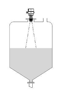
Advantage 1: Narrow, Focused Measurement Beam
Beam focusing is one of the main advantages of high-frequency radar in bulk-solid applications.
A tightly focused beam allows the sensor to observe a relatively small part of the material surface instead of illuminating a large portion of the silo.
This helps reduce reflections from:
- Silo walls
- Structural beams
- Internal ladders
- Filling equipment
- Nearby pipes
- Other fixed obstructions
The advantage becomes increasingly important in narrow or tall silos.
It is also useful when the sensor cannot be installed exactly at the geometric center of the vessel.
Advantage 2: Better Target Selection on Uneven Surfaces
Wood chips do not provide one perfectly horizontal reflecting surface.
A radar may receive reflections from several areas of the pile.
High-frequency radar combined with modern signal processing can help identify and track the most useful material echo as the pile moves during filling and discharge.
This does not turn the instrument into a three-dimensional scanner.
Instead, it improves the reliability of continuous distance measurement along the selected beam path.
Advantage 3: Non-Contact Measurement
Radar is installed above the material.
No measuring cable, mechanical float, or probe needs to extend through the entire chip pile.
This provides several practical benefits:
- No mechanical wear from moving wood chips
- No long sensing element buried in the material
- Reduced risk of damage during filling
- Easier top-mounted installation
- Lower direct contact with the process material
For large silos where maintenance access is difficult, these advantages can be significant.
Advantage 4: Good Performance in Dust
Dust can make wood-chip storage difficult for some measurement technologies.
Radar does not depend on sound propagation through the air space.
Industrial bulk-solid radar is therefore widely used in dusty silos containing powders, granules, minerals, and other solids.
For wood chips, the same principle is valuable during conveyor filling and active material movement.
The radar still needs a clean enough antenna surface to transmit and receive effectively, so severe dust buildup should be considered during installation and maintenance planning.
Advantage 5: Suitable for Long Measuring Distances
Large silos require sufficient signal strength at low material levels.
High-frequency radar instruments designed specifically for bulk solids can provide long measuring ranges while maintaining focused beam characteristics.
The required range should always be selected according to the actual silo dimensions.
A very long catalog range does not automatically improve measurement in a short silo.
The better approach is to select the instrument based on:
- Silo height
- Silo diameter
- Material reflectivity
- Surface angle
- Dust conditions
- Installation geometry
- Required accuracy
- Internal structures
JWrada-34 Radar Level Meter for Wood Chip Applications
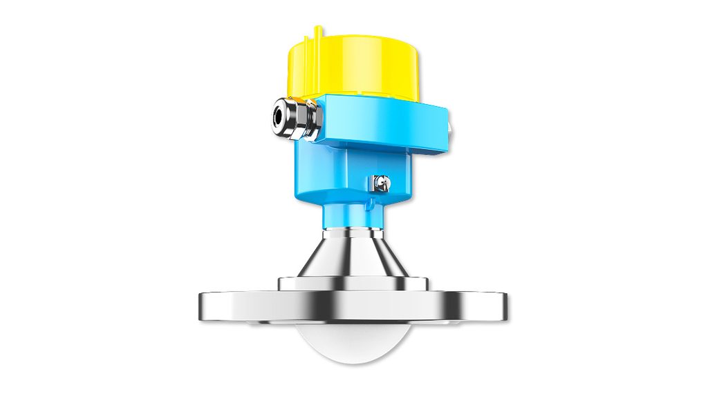
For difficult bulk-solid applications, the Jiwei JWrada-34 Radar Level Meter can be considered.
The instrument is designed for solid and complex level measurement applications and uses 80 GHz FMCW radar technology.
Its configuration includes a 76 mm lens antenna to provide focused radar transmission.
The current JWrada-34 design also includes features particularly relevant to bulk-solid silos:
- Narrow radar beam
- Non-contact measurement
- Universal adjustable flange
- Air-purge arrangement
- Echo-learning and false-echo processing
- Long measuring capability
- Continuous signal output for automation systems
The JWrada-34 has a specified maximum measuring range of up to 150 m.
However, this specification should not be interpreted to mean that every wood-chip silo can automatically be measured over that entire distance.
Actual performance depends on the target material, surface geometry, antenna direction, dust, installation arrangement, internal structures, and required measurement quality.
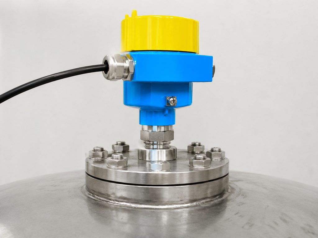
For a wood chip silo, the adjustable flange can be especially useful because the antenna may need to be aimed toward the preferred measuring area rather than simply pointing vertically downward.
The air-purge option may also help in installations where dust accumulation around the antenna is an important maintenance concern.
Why Adjustable Radar Alignment Matters
A liquid surface is normally horizontal.
A bulk-solid surface is not.
This difference explains why antenna alignment is particularly valuable for silo applications.
If the chip pile slopes away from the radar, part of the reflected energy may be directed away from the antenna.
By adjusting the sensor angle, engineers can aim the radar toward a more favorable part of the pile.
The best target is not necessarily the highest point.
Instead, it should be an area that provides a stable and representative surface through normal filling and emptying conditions.
An adjustable mounting arrangement can therefore improve installation flexibility.
Where Should the Radar Be Installed?
Correct mounting can be as important as the radar itself.
Avoid the Filling Stream
Do not install the radar directly above falling wood chips when another suitable location is available.
The filling stream can:
- Block the normal measurement path
- Create temporary strong echoes
- Produce heavy dust
- Create a local pile that does not represent overall inventory
Choose a position with a clearer view of the stored material.
Do Not Automatically Mount at the Center
For liquid tanks, center mounting may sometimes be convenient.
For a chip silo, the best position depends on:
- Filling location
- Discharge location
- Expected pile shape
- Silo diameter
- Structural members
- Measurement objective
The ideal position should be determined from the real silo geometry.
Check the Entire Beam Path
The beam path should be evaluated from the sensor down to the lowest expected material level.
A beam that looks clear near the roof may intersect a support, ladder, chute, or other structure farther down.
A vessel drawing is extremely useful during this evaluation.
Aim Toward a Representative Surface
The radar should ideally observe a part of the pile that remains measurable during both filling and discharge.
Avoid aiming directly at an extreme filling peak unless maximum pile height is specifically the measurement objective.
Likewise, avoid a deep discharge funnel if it creates a level trend that does not represent the required process measurement.
Protect the Antenna from Direct Material Impact
Wood chips should not strike the radar antenna directly.
Mechanical impact can damage the instrument or create excessive contamination.
The sensor should be mounted outside the normal material trajectory.
Inventory Measurement vs. Process-Control Measurement
One of the most important questions in wood-chip measurement is:
What will the level signal be used for?
The answer affects sensor placement.
Process-Control Measurement
For process control, operators may primarily need to know whether the chip level is rising, falling, approaching a high limit, or becoming too low.
A stable continuous trend may be more important than calculating exact tonnage.
Typical uses include:
- Conveyor start/stop logic
- Reclaim control
- High-level warning
- Low-level warning
- Maintaining downstream supply
Inventory Measurement
Inventory calculation is more complicated.
Because the wood-chip surface is uneven, converting one measured height into total volume introduces uncertainty.
Additional uncertainty may come from:
- Bulk-density variation
- Moisture variation
- Compaction
- Irregular pile shape
- Bridges and voids
A single radar level transmitter can provide excellent continuous level information, but it should not automatically be assumed to provide laboratory-grade mass inventory.
Where highly accurate bulk inventory is required, the complete measurement and volume-conversion strategy should be evaluated separately.
This distinction is important when defining performance expectations.
Radar vs. Ultrasonic Measurement for Wood Chips
Ultrasonic instruments also provide non-contact measurement.
They transmit sound waves toward the material surface and calculate distance from the return time.
For smaller and relatively simple bins, ultrasonic technology may provide an economical solution.
However, wood chip silos can introduce conditions that make radar attractive.
These include:
- Heavy dust
- Long measuring distances
- Uneven surfaces
- Narrow vessels
- Internal structures
- Difficult beam alignment
Ultrasonic measurement depends on acoustic propagation through the atmosphere inside the silo.
Radar uses electromagnetic waves.
High-frequency radar can also provide a more tightly focused beam than many conventional ultrasonic instruments.
For demanding wood-chip storage, these characteristics often make radar the preferred continuous measurement technology.
The final choice should still be application-driven rather than based only on sensor type.
Radar Level Measurement vs. Point Level Detection
Continuous radar and point level switches perform different jobs.
A radar transmitter provides the current material level continuously.
A point level switch indicates whether material has reached a specific position.
A wood-chip silo may therefore use:
Continuous radar for:
- Inventory trend
- Process control
- Conveyor management
- Operator display
- PLC or DCS monitoring
Independent point detection for:
- High-level alarm
- High-high overfill protection
- Low-level alarm
- Empty-bin detection
Where overfilling presents significant operational or safety consequences, an independent high-level device may provide an additional protection layer.
What Information Should Be Provided Before Selecting a Wood Chip Level Sensor?
For a reliable radar recommendation, provide:
- Silo height
- Silo diameter
- Silo shape
- Roof geometry
- Maximum and minimum operating level
- Wood-chip type and approximate size
- Moisture condition
- Filling method
- Filling-point location
- Discharge-point location
- Expected pile shape
- Dust conditions
- Internal structures
- Existing mounting opening
- Available flange or connection
- Hazardous-area classification, if applicable
- Required output signal
- Control-system requirements
- Required measurement accuracy
- Existing measurement problems
A drawing showing the filling chute, discharge position, internal structures, and proposed radar location can be particularly valuable.
Hazardous-Area Considerations
Wood dust should not be treated simply as a measurement inconvenience.
Depending on the process, particle characteristics, concentration, ventilation, and plant classification, combustible dust may create hazardous-area requirements.
Instrumentation must therefore match the site’s actual electrical and explosion-protection classification.
Do not select an explosion-protected radar only because the catalog contains a hazardous-area version.
The required certification, protection method, temperature class, installation method, grounding, cable entries, and local regulatory requirements should all be confirmed for the project.
Maintenance Considerations
Non-contact radar can reduce mechanical wear, but it should not be described as maintenance-free.
Periodic inspection should consider:
- Dust accumulation on the antenna
- Condition of the air-purge system
- Mounting security
- Sensor alignment
- Cable condition
- Housing sealing
- Process connection
- Echo quality
- Stored false-echo map
- Changes to silo internals
The measurement should also be reviewed if the filling arrangement is modified.
Moving a conveyor, changing the chute direction, or adding an internal structure can change the radar echo environment.
Why Correct Installation Matters More Than Maximum Range
It is easy to focus on the maximum measuring range when comparing bulk-solid radar instruments.
But a wood-chip silo that is only a fraction of the sensor’s maximum range can still produce poor measurement if the radar is installed incorrectly.
For example, a long-range sensor may still struggle if:
- The beam points directly at a wall
- The sensor looks into the filling stream
- A structural beam blocks the target
- The antenna is poorly aligned with the sloped surface
- Heavy deposits cover the antenna
- The configured measuring range is incorrect
Reliable measurement therefore comes from combining suitable hardware with good application engineering.
The highest specification is not automatically the best measurement solution.
Conclusion
Wood chip silo level measurement is a demanding bulk-solid application in pulp and paper production.
Unlike a liquid tank, a chip silo contains a constantly changing material surface.
Filling creates peaks and sloped piles.
Discharge can create funnels and channels.
Wood chips can bridge.
Dust may fill the headspace.
Tall silos can require long-distance measurement, while structural members and filling equipment can create additional interference.
These conditions explain why modern 80 GHz radar level measurement is well suited to many wood-chip silos.
Its narrow beam helps isolate a useful measuring area.
Non-contact measurement avoids placing long sensing elements inside moving chips.
Focused radar transmission helps reduce interference from silo walls and internal structures, while modern echo processing supports stable tracking of changing bulk-solid surfaces.
For demanding installations, the Jiwei JWrada-34 provides a bulk-solid-oriented radar configuration with 80 GHz FMCW technology, a focused lens antenna, adjustable mounting, air-purge capability, and long measuring range.
However, even a high-performance radar cannot compensate for every installation problem.
The sensor should be positioned away from the filling stream, aimed toward a representative material surface, protected from direct impact, and configured according to the actual silo geometry.
For the best result, provide the silo dimensions, filling and discharge positions, expected pile shape, dust conditions, internal structures, mounting details, and control requirements before selecting the instrument.
The goal is not simply to measure the longest possible distance.
The goal is to obtain a stable, representative, and useful level signal throughout the real operating cycle of the wood-chip silo.
Frequently Asked Questions
What is the best level sensor for a wood chip silo?
High-frequency non-contact radar is a strong option for many wood chip silos because it can handle uneven bulk-solid surfaces, dust, long measuring distances, and complex silo structures. Final selection should still consider silo geometry, filling position, material properties, and installation conditions.
Can radar measure wood chips through dust?
Radar can perform well in dusty bulk-solid applications because it uses electromagnetic waves rather than sound. Heavy dust buildup directly on the antenna can still affect performance, so mounting position and antenna maintenance should be considered.
Why is 80 GHz radar useful for wood chips?
80 GHz radar can create a narrow, focused measurement beam. This helps the sensor avoid silo walls, structural members, filling equipment, and other unwanted reflections while targeting a selected part of the wood-chip surface.
Can radar measure an uneven wood-chip surface?
Yes. Radar measures the distance to the material surface within its measuring area. Because wood chips form slopes, peaks, and valleys, correct sensor position and alignment are important.
Should the radar be installed directly above the filling point?
Normally no. Falling material, heavy dust, and the local filling peak can make measurement more difficult. A position with a clearer and more representative view of the stored chips is usually preferred.
Can one radar sensor calculate the exact amount of wood chips in the silo?
A radar sensor provides continuous surface-distance or level information. Converting that measurement into exact volume or mass can be more difficult because the chip surface is irregular and bulk density can vary. Highly accurate inventory applications may require additional engineering.
Can radar detect a bridge or empty space underneath the chips?
A conventional top-mounted radar primarily measures the visible upper material surface. It cannot automatically identify every hidden void underneath a bridge. Bridging and silo-flow problems should be addressed separately.
Is ultrasonic level measurement suitable for wood chips?
Ultrasonic technology may work in simpler bins with moderate dust and suitable measuring distances. High-frequency radar is often preferred for demanding applications involving heavy dust, long range, narrow silos, or complex internal structures.
Why is an adjustable flange useful for a wood chip silo?
The wood-chip surface is usually sloped rather than horizontal. An adjustable flange allows the radar antenna to be aimed toward a more suitable area of the pile, which can improve echo quality and measurement stability.
Does a wood chip silo require an explosion-proof radar?
Not every silo has the same classification. Wood dust can create combustible-dust hazards under certain conditions, so the required hazardous-area certification should be determined from the site’s actual classification and local regulations.
Is the JWrada-34 suitable for wood chip silo level measurement?
The JWrada-34 is designed for demanding bulk-solid measurement and uses 80 GHz FMCW radar with a focused lens antenna, adjustable flange, and air-purge arrangement. Final suitability should be confirmed using the actual silo height, geometry, dust conditions, mounting position, hazardous-area requirements, and control-system needs.