
In industries such as oil and gas, petrochemicals, water and wastewater treatment, food and beverage, pharmaceuticals, power generation, energy, storage terminals, and process automation, radar level transmitters have become one of the most widely used instruments for level measurement.
Most users have a straightforward understanding of how they work: install a radar level transmitter on top of a tank, and it measures the liquid level inside.
From a technical perspective, however, that description is not entirely accurate.
What a radar level transmitter directly measures is not the liquid level itself. It measures the distance from the radar reference point or antenna to the surface of the process medium. The level value displayed on the instrument, PLC, DCS, or control system is calculated from that measured distance using parameters such as tank height, zero point, full-scale point, and measurement range.
Understanding this distinction is fundamental to understanding how radar level measurement works, how a radar level transmitter should be installed and configured, and how measurement problems should be diagnosed.
1. What Does a Radar Level Transmitter Actually Measure?
If we break down the measurement process of a radar level transmitter, its fundamental task is relatively simple:
Transmit a radar signal → receive the echo → identify the material surface → calculate the distance.
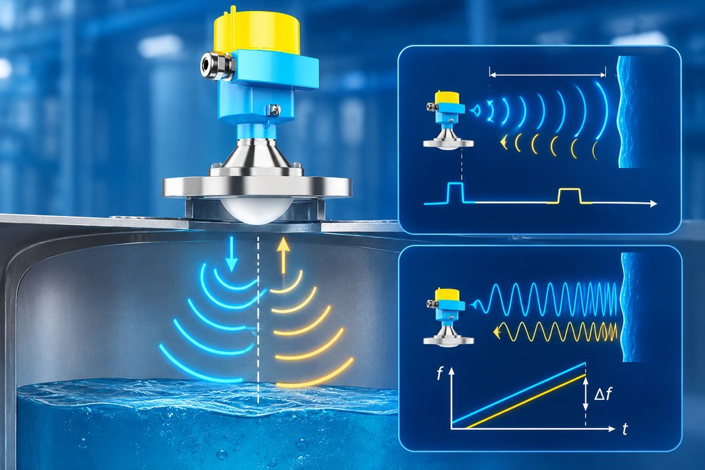
When a radar level transmitter is installed on top of a storage tank, vessel, reactor, or silo, its antenna transmits high-frequency electromagnetic waves toward the process medium.
When the radar waves reach the surface of a liquid or bulk solid, the difference in dielectric properties between the air or vapor space and the process material causes part of the electromagnetic energy to be reflected.
The radar receives this reflected signal and analyzes the relationship between the transmitted and received signals to determine the distance between the radar reference point and the material surface.
Therefore, at the most fundamental measurement level:
A radar level transmitter measures distance—not level.
Suppose the reference height of a tank is H, while the distance measured from the radar reference point to the liquid surface is D. The liquid level L can generally be expressed as:
L = H − D
For example, assume the distance from the radar reference point to the bottom of a tank is 10 meters.
If the radar detects that the liquid surface is 3 meters below the reference point:
Level = 10 m − 3 m = 7 m
The instrument may display a level of 7 meters, but the radar itself has directly measured a distance of 3 meters.
This is why parameters such as empty tank height, zero point, full point, blocking distance, reference point, and measuring range are so important when configuring a radar level transmitter.
If these parameters are incorrect, the radar may measure the distance perfectly while still displaying an incorrect level.
2. How Does Radar Determine Distance?
To understand a radar level transmitter, we first need to understand one basic principle:
Electromagnetic waves travel extremely fast—approximately at the speed of light in air.
A radar level transmitter sends electromagnetic energy toward a target and receives the reflected signal. By analyzing the propagation characteristics of that signal, the instrument can determine how far away the target is.
Different types of radar level transmitters use different signal-processing methods.
Traditional pulse radar, for example, can determine distance by analyzing the propagation time of electromagnetic pulses.
Many modern industrial radar level transmitters, especially FMCW radar level transmitters, use Frequency Modulated Continuous Wave technology. The transmitter continuously changes the frequency of the emitted radar signal and analyzes the frequency difference between the transmitted signal and the returning echo.
That frequency difference is related to the distance of the reflecting surface.
Regardless of the specific radar technology, the fundamental logic remains the same:
First identify the surface of the process medium, then determine how far that surface is from the radar reference point.
From a signal-processing perspective, “measuring level” can therefore be divided into three questions:
- What target did the radar wave hit?
- Which echo represents the actual product surface?
- How far is that surface from the radar reference point?
Only when all three questions are answered correctly can the instrument provide a reliable level measurement.

3. The Hardest Part Is Often Not Measuring Distance, but Finding the Real Surface
Many people assume that the key technology behind a radar level transmitter is its ability to calculate distance accurately.
In real industrial applications, distance calculation itself is often not the most difficult part.
The greater challenge is:
How does the instrument identify the real product surface among multiple competing echoes?
Under ideal conditions, imagine a simple cylindrical tank with no internal structures, no agitator, no foam, no vapor, and a perfectly calm liquid surface.
The echo profile would be relatively simple.
Real process vessels, however, are rarely that simple.
Inside a tank there may be:
- Agitators
- Heating coils
- Manways
- Support beams
- Inlet pipes
- Internal ladders
- Weld seams
- Spray devices
- Foam
- Vapor
- Turbulent surfaces
When radar energy reaches these objects, they may also produce reflections.
As a result, a radar level transmitter may receive not one simple echo but a complete echo curve containing multiple reflections with different amplitudes and positions.
The instrument then has to determine:
Is this echo coming from the liquid surface or from a support beam?
Is the strongest reflection the actual product surface or the agitator?
Why did the previous surface echo disappear as the level changed?
If several echoes are present simultaneously, which one should the instrument track?
This is where echo processing algorithms, false echo suppression, signal tracking, and dynamic echo recognition become extremely important.
For this reason, evaluating a radar level transmitter solely on a specification such as “±1 mm accuracy” can be misleading.
Under difficult process conditions, the ability to consistently identify and track the correct echo can be more important than theoretical ranging accuracy under laboratory conditions.
4. Why Do Different Media Produce Different Radar Echo Strengths?
The ability of a radar level transmitter to detect a material surface reliably is closely related to an important property:
Dielectric constant, also known as relative permittivity.
In simplified terms, the dielectric properties of a medium influence how strongly radar energy is reflected at the interface between the vapor space and the material.
Generally, the greater the dielectric contrast between the gas phase and the process medium, the easier it is for the radar to obtain a strong, identifiable reflection.
Water, for example, normally provides favorable radar reflection characteristics. For this reason, measuring water level is relatively straightforward for most industrial radar level transmitters.
Some low-dielectric-constant liquids, including certain oils, solvents, and light hydrocarbons, may produce weaker surface reflections.
If weak surface echoes occur together with reflections from the tank bottom, internal structures, or other interference sources, identifying the correct echo becomes more difficult.
Therefore, when selecting a radar level transmitter, asking only:
“What is the maximum measuring range?”
is not enough.
More useful questions include:
What is the process medium? What is its approximate dielectric constant? Is there an agitator? Is foam present? Are there heating coils or other internals? Where will the antenna be installed?
All of these factors can influence the quality of the radar echo and ultimately the reliability of the level measurement.
5. Why Can a Radar Level Transmitter “See” the Tank Bottom?
This is an interesting phenomenon frequently encountered during commissioning.
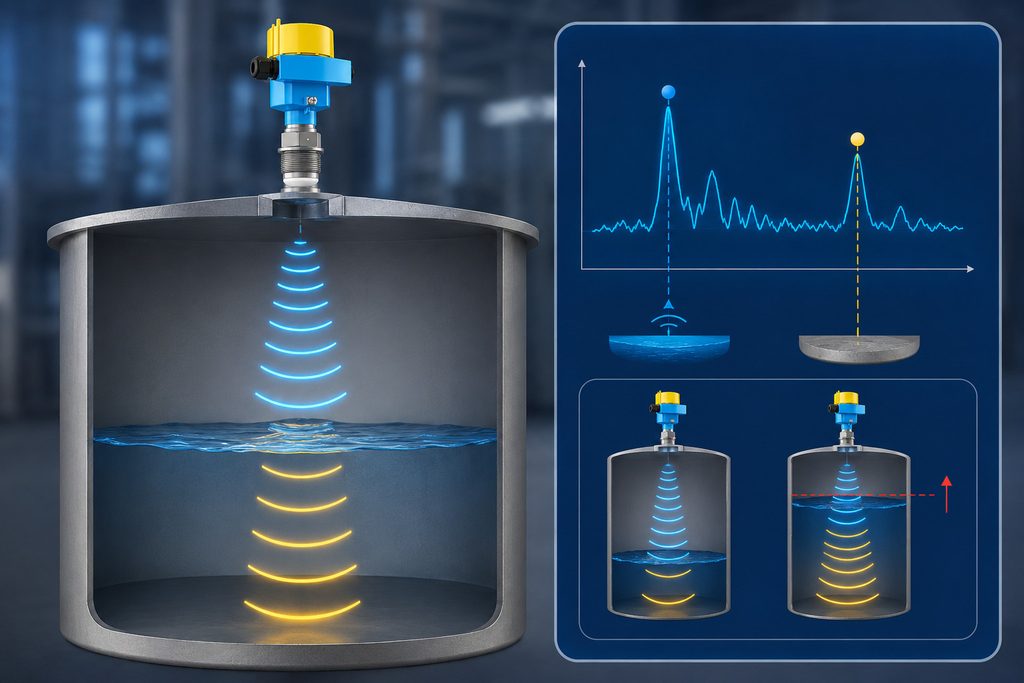
When the liquid level is low, particularly when measuring a medium with a relatively low dielectric constant, not all of the radar energy is necessarily reflected at the liquid surface.
Some radar energy may penetrate the medium, travel to the tank bottom, and then be reflected back toward the antenna.
The echo curve may therefore contain both:
a liquid surface echo and a tank-bottom echo.
If the radar’s signal-processing algorithm identifies the wrong target, it may mistake the tank-bottom reflection for the actual liquid surface.
This can create apparently strange behavior.
For example, there may still be liquid inside the tank, but the radar indicates a level close to zero. Alternatively, when the liquid level changes, the displayed value may suddenly jump toward the tank bottom.
This does not necessarily mean that the radar is incapable of measuring the liquid.
Instead:
The instrument may have locked onto the wrong echo.
This is why checking the radar echo curve or echo profile is extremely useful during commissioning and troubleshooting.
If you look only at the displayed level value, it may be difficult to determine what is happening. Once the echo curve is examined, however, the operator may be able to distinguish the product surface echo, false echoes, noise, and possible tank-bottom reflections.
6. Why Does Installation Position Directly Affect Radar Level Measurement?
Because radar level measurement depends on the propagation and reflection of electromagnetic waves, the physical environment in front of the antenna is extremely important.
This is why a radar level transmitter should not simply be installed on whichever tank nozzle happens to be most convenient.
If the radar is installed too close to the tank wall, part of the radar beam may interact with the wall.
If the antenna is positioned directly above an inlet, incoming material may continuously disturb the surface or interfere with the radar signal.
If agitator shafts, pipes, beams, or other structures are located within the radar beam, they may generate strong false echoes.
The issue becomes even more interesting when measuring bulk solids.
Unlike liquids, the surface of a solid material is rarely horizontal.
Materials such as cement, coal, grain, minerals, powders, and plastic pellets may form cones, slopes, or irregular surfaces inside a silo.
In these applications, what the radar actually measures is:
the distance to an effective reflecting surface within the radar beam.
Therefore, installing a radar transmitter in the center of a silo may produce a different measurement from installing it off-center.
This does not automatically mean that the instrument is inaccurate. The measured target itself may simply not be a flat surface.
The installation position of a radar level transmitter is therefore not merely a mechanical consideration.
It determines the measurement geometry—in other words, what the radar can actually “see.”
7. When the Liquid Surface Is Moving, Which “Level” Does the Radar Measure?
When a tank contains an agitator or experiences high-speed filling, the liquid surface may be continuously moving.
Strictly speaking, there may no longer be one perfectly defined horizontal liquid surface.
So what does the level displayed by the radar actually represent?
Typically, the radar identifies and tracks valid echoes within its measurement window. Internal filtering, averaging, damping, and signal-processing algorithms are then used to produce a relatively stable process value.
Therefore, the displayed level is not necessarily the highest or lowest point of the liquid surface at a particular instant.
It is better understood as:
the effective surface position determined by the instrument after echo recognition, target tracking, and signal processing.
This also explains why radar level transmitters normally include settings for damping time or response speed.
A longer damping time produces a more stable output but responds more slowly to rapid level changes.
A shorter damping time allows the instrument to follow rapid changes more closely, but a turbulent surface may cause a more active or fluctuating output.
In other words, a radar level transmitter does not simply “see the liquid and report a number.”
It continuously performs target identification and tracking.
8. Why Can Foam Affect Radar Level Measurement?
Foam is one of the classic challenging applications for radar level measurement.
A common question is:
Does the radar measure the top of the foam or the actual liquid surface underneath it?
There is no universal answer.
The result depends on factors such as foam thickness, density, moisture content, process medium, and radar frequency.
Some light, dry, and loosely structured foams may allow a significant amount of radar energy to penetrate through them. In such cases, the radar may detect the liquid surface underneath.
Dense or wet foam, on the other hand, may generate a stronger reflection of its own, causing the radar to detect a position closer to the top of the foam layer.
In other cases, foam may absorb or scatter radar energy, significantly weakening the useful return signal.
Therefore, the statement that:
“Radar is completely unaffected by foam”
is too absolute.
A more technically accurate statement would be:
Radar level transmitters can perform well in many foaming applications, but actual performance depends on the characteristics of the foam, process medium, radar technology, and installation conditions.
9. Why Is Understanding “Radar Measures Distance” Important for Troubleshooting?
Once this concept is understood, many common radar level transmitter problems become much easier to diagnose.
Suppose the displayed level is consistently 500 mm higher or lower than the actual level.
The first assumption should not necessarily be that the radar has a 500 mm measurement error.
Instead, check questions such as:
Is the tank reference height configured correctly?
Is the correct radar reference point being used?
Is the zero point correct?
Has the height of the mounting nozzle been considered correctly?
Are the transmitter output range and PLC/DCS scaling consistent?
If one of these parameters contains a 500 mm error, the radar may be measuring distance accurately while the calculated level is incorrect.
Consider another example.
Suppose the displayed level suddenly jumps from 6 meters to 2 meters.
The next step should be to examine the echo profile and determine whether the radar has lost the original product surface echo and locked onto an internal structure or another false reflection.
A useful troubleshooting principle is therefore:
First verify whether the measured distance is correct. Then verify whether that distance is being converted into level correctly.
Do not immediately conclude that the radar sensor itself is inaccurate simply because the final displayed level is wrong.
10. Why Are 80 GHz Radar Level Transmitters Becoming So Common?
In recent years, 80 GHz radar level transmitters and other high-frequency radar instruments have become increasingly common in process industries.
One major reason is their ability to produce a relatively narrow radar beam.
A narrower beam concentrates radar energy into a smaller area and reduces the probability of illuminating tank walls, pipes, support structures, and other potential sources of false echoes.
This can be particularly valuable for:
- Small storage tanks
- Narrow vessels
- Reactors with agitators
- Vessels with complex internals
- Silos with restricted installation positions
For example, if a radar transmitter has a relatively wide beam, the antenna may simultaneously receive reflections from the liquid surface, tank wall, and internal support structures.
A narrow-beam radar can focus more of its energy on the intended measurement area, reducing certain interference echoes through improved measurement geometry.
However, one important point should be emphasized:
A higher radar frequency does not automatically mean better performance in every application.
Radar level transmitter selection should still consider measuring range, process medium, dielectric properties, pressure, temperature, foam, dust, condensation, antenna design, nozzle dimensions, and installation conditions.
Reliable radar level measurement is never simply a question of choosing the highest GHz value.
11. The Displayed “Level” Is Actually the Result of a Measurement Chain
If we summarize the entire process, a radar level transmitter produces a level value through approximately the following measurement chain:
Radar signal transmission → electromagnetic wave propagation → surface reflection → echo reception → echo identification → distance calculation → parameter conversion → level output
Therefore, when an instrument displays a value such as:
Level: 6.352 m
that simple number is actually the result of multiple stages of electromagnetic measurement, signal processing, target identification, and mathematical calculation.
From this perspective:
A radar level transmitter is not simply a sensor that directly measures liquid level. It is a non-contact measurement system that determines the distance to a material surface and then converts that distance into a level or bulk-solid level value.
Once this principle is understood, many other concepts related to radar level measurement become easier to understand.
Why must the reference height be configured accurately?
Because the level is calculated from the measured distance.
Why is the installation position so important?
Because the installation position determines which targets the radar can see.
Why should engineers examine the echo curve?
Because before the level can be correct, the instrument must first identify the correct material surface.
Why is false echo suppression sometimes necessary in complex tanks?
Because internal structures can also reflect radar signals.
Why are low-dielectric media more challenging?
Because the true surface echo may be relatively weak.
12. Conclusion: Understand the Distance, and You Understand Radar Level Measurement
For everyday use, there is nothing wrong with saying that a radar level transmitter is an instrument that “measures liquid level.”
For instrumentation engineers, automation engineers, maintenance technicians, and professionals responsible for radar level transmitter selection, installation, commissioning, and troubleshooting, however, a more precise understanding is essential:
A radar level transmitter first measures the distance from its reference point to the surface of the process medium. It then converts that distance into liquid level or material level using configured tank geometry and measurement parameters.
This seemingly small distinction runs through the entire technical logic of radar level measurement.
Reliable performance depends not only on ranging accuracy, but also on whether the radar signal can effectively reach the material surface, whether the surface generates a sufficiently identifiable echo, whether the instrument correctly recognizes and tracks that echo, and whether the tank configuration parameters are accurate.
So the next time a radar level reading appears to be incorrect, instead of immediately asking:
“Why is the radar level transmitter measuring the level incorrectly?”
ask a more useful technical question:
“What distance is the radar actually measuring right now—and which echo is it tracking?”
The answer to many seemingly complicated radar level measurement problems can often be found there.

