
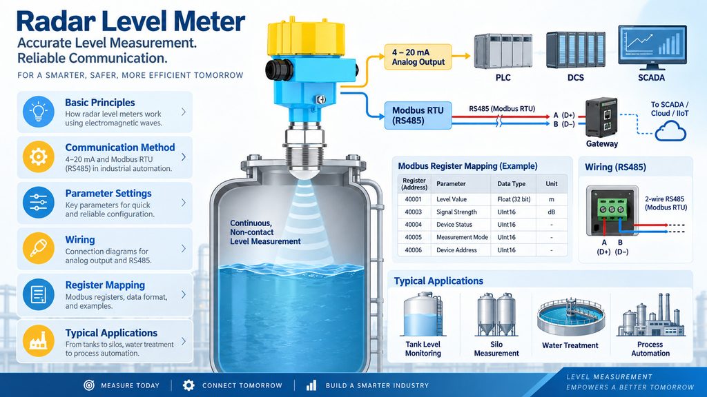
In industrial automation systems, a radar level meter not only needs to measure the level of liquids or bulk solids accurately, but also needs to transmit the measurement data reliably to PLCs, DCS systems, SCADA platforms, gateways, or other control systems.
In addition to the traditional 4–20 mA analog output, more and more radar level meters now support Modbus RTU communication.
So, what exactly is Modbus RTU in a radar level meter? What is the relationship between Modbus RTU and RS485? How should it be wired and configured in a real industrial application?
This article explains the basic principles, communication method, parameter settings, wiring, register mapping, and typical applications of Modbus RTU in radar level measurement systems.
What Is a Radar Level Meter?
A radar level meter is a non-contact instrument used to measure the level of liquids or bulk solids by using electromagnetic waves.
During operation, the antenna of the radar level meter transmits radar signals toward the surface of the measured medium. When the electromagnetic wave reaches the surface of the liquid, powder, granule, or other material, part of the signal is reflected back to the sensor.
The radar level meter receives the reflected signal and calculates the distance between the sensor and the material surface based on the travel time or frequency change of the radar wave.
Common radar level measurement technologies include:
- Pulse radar
- FMCW radar
- 26 GHz radar level meters
- 80 GHz radar level meters
- Higher-frequency radar sensors such as 120 GHz devices
Because radar measurement is generally less affected by changes in temperature, pressure, gas density, or vapor conditions, radar level meters are widely used in industries such as water treatment, chemical processing, petroleum, food and beverage, pharmaceuticals, power generation, cement, and mining.
However, measuring the level is only the first step.
The measured data must also be transmitted to an automation or control system. This is where Modbus RTU becomes important.
What Is Modbus RTU?
Modbus RTU is an industrial serial communication protocol.
Modbus was originally developed for communication between PLCs and industrial devices. Over time, it became one of the most widely used communication protocols in industrial automation.
A simple way to understand Modbus RTU is to think of it as a standardized language used between a radar level meter and a PLC.
For example, a PLC may send a request such as:
“Please tell me the current level.”
The radar level meter responds according to the Modbus RTU protocol:
“The current level is 5.36 meters.”
Because both devices follow the same communication rules, equipment from different manufacturers can exchange data more easily.
This interoperability is one of the main reasons Modbus RTU remains popular in industrial applications.
Are Modbus RTU and RS485 the Same Thing?
No. This is one of the most common points of confusion.
RS485 is an electrical communication standard, while Modbus RTU is a communication protocol.
They are related, but they are not the same.
A useful analogy is:
RS485 is the road, while Modbus RTU is the traffic rule used on that road.
RS485 mainly defines how electrical signals are transmitted between devices, including aspects such as:
- Electrical signal levels
- Differential communication
- Cable connection
- Multi-device communication
- Long-distance serial transmission
Modbus RTU defines how devices communicate logically, including:
- How the master sends a request
- How the slave responds
- How device addresses are defined
- How data is organized
- How communication errors are checked
This is why many radar level meters are described as supporting:
RS485 / Modbus RTU
This usually means the device uses an RS485 physical interface and communicates using the Modbus RTU protocol.
Why Do Radar Level Meters Use Modbus RTU?
Traditional radar level transmitters often use a 4–20 mA analog output.
For example:
4 mA = 0 m
20 mA = 10 m
The PLC receives the current signal and converts it into the corresponding level value.
This method is simple and reliable, but the amount of information that can be transmitted is limited.
With Modbus RTU, a radar level meter can provide much more information.
Depending on the manufacturer and model, available data may include:
- Current level
- Measured distance
- Level percentage
- Echo strength
- Sensor temperature
- Instrument status
- Alarm or fault codes
- Empty calibration distance
- Full calibration distance
- Damping time
- Device address
- Firmware version
For industrial systems that require digital monitoring, remote diagnostics, or centralized data acquisition, Modbus RTU provides much more information than a basic analog output.
How Does Modbus RTU Work in a Radar Level Meter?
A typical Modbus RTU network uses a master-slave communication structure.
For example:
PLC = Master
Radar level meter = Slave
The PLC actively sends a request to a specific radar level meter.
Suppose the Modbus address of the radar level meter is:
01
The PLC may send a request to read a certain register from device 01.
After receiving the request, the radar level meter checks several items:
- Whether the device address matches its own address
- Whether the function code is valid
- Whether the requested register address exists
- Whether the CRC checksum is correct
If everything is valid, the radar level meter sends the requested data back to the PLC.
This is the basic communication process of a Modbus RTU master-slave system.
What Is a Modbus Address?
Multiple radar level meters can be connected to the same RS485 communication bus.
For this reason, each device must have a unique Modbus address.
For example:
Tank 1 radar level meter: Address 1
Tank 2 radar level meter: Address 2
Tank 3 radar level meter: Address 3
If the PLC sends a request to address 2, only the second radar level meter should respond.
This makes it possible for several field instruments to share one RS485 communication line, which can significantly reduce cabling and PLC input requirements.
One important rule is:
Two devices on the same Modbus network should not use the same slave address.
Duplicate addresses can cause communication conflicts, unstable data, or complete communication failure.
Common Modbus RTU Communication Parameters
Before connecting a radar level meter to a PLC or industrial gateway, several communication parameters usually need to be configured.
1. Baud Rate
Common baud rates include:
- 4800 bps
- 9600 bps
- 19200 bps
- 38400 bps
- 57600 bps
- 115200 bps
In many industrial applications, 9600 bps and 19200 bps are commonly used.
The baud rate of the PLC and the radar level meter must match.
2. Data Bits
Modbus RTU normally uses:
8 data bits
3. Parity
Common parity settings include:
- None
- Even
- Odd
A typical communication setting may be written as:
9600, 8, N, 1
This means:
9600 baud, 8 data bits, no parity, and 1 stop bit.
4. Slave Address
The slave address is also called the Modbus Device ID or Modbus Slave ID.
Each radar level meter on the same network must have a unique address.
What Is a Modbus Register?
In Modbus RTU communication, data is usually stored in different registers.
A register can be understood as a specific data location inside the radar level meter.
For example, a manufacturer may define:
40001: Level value
40003: Distance value
40005: Sensor temperature
40007: Echo strength
40009: Device status
If the PLC needs to read the level value, it reads the corresponding register.
However, there is an important point:
Modbus register addresses are not always the same between different manufacturers or models.
Before programming the PLC, the user should check the manufacturer’s:
Modbus Register Map
The register map usually provides information such as:
- Register address
- Data type
- Measurement unit
- Read/write permission
- Scaling factor
- Supported function code
Common Modbus Function Codes
A Modbus function code tells the slave device what operation the master wants to perform.
Common function codes used with radar level meters include:
Function Code 03: Read Holding Registers
This function is used to read holding registers.
It is one of the most commonly used function codes for reading radar level data.
Function Code 04: Read Input Registers
This function is used to read input registers.
Some manufacturers store real-time measurement values in input registers instead of holding registers.
Function Code 06: Write Single Register
This function writes a value to one register.
It may be used to modify certain configurable parameters if remote configuration is allowed.
Function Code 16: Write Multiple Registers
This function writes values to multiple registers at the same time.
The exact function codes supported by a radar level meter should always be confirmed in the manufacturer’s Modbus communication manual.
How to Wire a Modbus RTU Radar Level Meter
Most Modbus RTU radar level meters use a two-wire RS485 interface.
Typical terminal labels include:
A / B
or:
D+ / D-
When several devices are connected, a daisy-chain or bus topology is normally preferred:
PLC → Radar Meter 1 → Radar Meter 2 → Radar Meter 3
A star topology is generally less desirable because improper branching can increase signal reflections and communication instability.
For long-distance communication or electrically noisy environments, the following practices are recommended:
- Use shielded twisted-pair cable
- Use proper grounding practices
- Keep communication cables away from high-power cables
- Avoid long parallel runs next to motors or variable-frequency drives
- Install termination resistors when required
- Confirm the polarity of the A and B terminals
A commonly used termination resistance is:
120 ohms
However, whether termination is necessary depends on factors such as cable length, baud rate, number of devices, network topology, and signal quality.
What Does CRC Do in Modbus RTU?
Industrial sites often contain strong sources of electrical interference, including motors, variable-frequency drives, relays, and high-power cables.
Communication data may therefore be affected by electromagnetic noise.
Modbus RTU uses a CRC, or Cyclic Redundancy Check, to help detect transmission errors.
The receiving device calculates the CRC value of the received data and compares it with the CRC included in the communication frame.
If the values match, the frame is considered valid.
If they do not match, the receiving device normally rejects the message.
This mechanism helps improve communication reliability in industrial environments.
Typical Applications of Modbus RTU Radar Level Meters
Radar level meters with RS485 Modbus RTU are particularly suitable for industrial sites that require multiple measuring points.
For example, a wastewater treatment plant may have dozens of tanks or basins.
If every radar level sensor uses a separate analog signal, the system may require a large amount of cabling and many PLC analog input modules.
With RS485 Modbus RTU, several radar level meters can share the same communication bus, allowing the PLC to collect level information from multiple locations through one digital communication network.
Typical applications include:
- Water tank level monitoring
- Wastewater tank level measurement
- Chemical storage tank monitoring
- Oil tank level measurement
- Cement silo level monitoring
- Fly ash silo measurement
- Grain silo level measurement
- River and reservoir water level monitoring
- Smart water management systems
- Industrial IoT data acquisition
Modbus RTU vs. 4–20 mA: Which One Should You Choose?
Neither communication method is always better than the other.
If the system only needs a single level value and simplicity is the main requirement, 4–20 mA remains a mature and reliable option.
If the system needs to read several parameters, such as level, distance, temperature, echo quality, and device status, or if several radar level meters need to be connected to the same network, Modbus RTU offers clear advantages.
Some radar level transmitters support both:
4–20 mA + RS485 Modbus RTU
In this type of system, the analog output can be used as the main process signal, while Modbus RTU is used for diagnostics, configuration, and additional process data.
This combination can improve both reliability and system visibility.
What Should You Check If Modbus RTU Communication Fails?
If a PLC cannot communicate with a radar level meter, several common issues should be checked.
First, confirm that the RS485 A and B wires are not reversed.
Next, verify that the communication parameters match between the PLC and the radar level meter, including:
- Baud rate
- Data bits
- Parity
- Stop bits
- Slave address
If the communication settings are correct, check the following:
- Is the Modbus function code correct?
- Is the register address correct?
- Is the data type correct?
- Is there an address offset issue?
- Is the 32-bit word order correct?
- Is the communication cable exposed to strong electrical interference?
- Is the communication distance too long?
- Are termination resistors installed correctly?
It is also common to use software such as Modbus Poll, ModScan, or similar Modbus testing tools to communicate directly with the radar level meter during troubleshooting.
This can help determine whether the problem is related to the instrument, wiring, communication settings, or PLC program.
Conclusion
Modbus RTU is one of the most common digital communication methods used in modern radar level meters.
It is typically implemented over an RS485 interface and allows PLCs, DCS systems, SCADA systems, and industrial gateways to read not only level values, but also distance, temperature, echo information, device status, and fault data.
The three most important concepts to remember are:
RS485 defines how the data is physically transmitted.
Modbus RTU defines how the devices communicate.
Modbus registers define what data is being read or written.
For simple single-point level measurement, 4–20 mA remains an effective and reliable solution.
For multi-device networking, remote diagnostics, industrial IoT, and digital process monitoring, an RS485 Modbus RTU radar level meter provides greater flexibility and access to more process information.
As industrial automation and smart manufacturing continue to develop, radar level meters with Modbus RTU communication are becoming increasingly common in tank level measurement, silo level monitoring, water level measurement, and other industrial applications.
FAQ About Radar Level Meter Modbus RTU
Is RS485 on a radar level meter the same as Modbus RTU?
Not exactly. RS485 is the physical communication interface, while Modbus RTU is the communication protocol. A device with RS485 does not automatically support Modbus RTU unless the manufacturer specifically states that it does.
How many radar level meters can be connected to one RS485 bus?
The practical number depends on the RS485 transceiver, network loading, cable length, baud rate, wiring topology, and communication environment. A system should not be designed only according to the theoretical maximum number of devices.
Can a PLC read a radar level meter directly?
Yes, in many cases. If the PLC supports RS485 Modbus RTU and the correct register map is available, it can usually communicate directly with the radar level meter.
Why is the level value read through Modbus incorrect?
Common causes include an incorrect register address, wrong data type, wrong scaling factor, register offset differences, or incorrect byte and word order for 32-bit values.
Is Modbus RTU suitable for long-distance communication?
RS485 is suitable for relatively long-distance industrial communication, but the actual usable distance depends on baud rate, cable quality, electrical noise, number of connected devices, and network topology.
For very long-distance or remote monitoring applications, RS485 can also be connected to gateways that convert Modbus RTU to Ethernet, Modbus TCP, cellular networks, or other industrial communication systems.

