
In chemical plants, water treatment facilities, boiler systems, oil storage terminals, and many other industrial sites, operators often require two types of liquid level information at the same time. They need a clear local indication beside the vessel, as well as a reliable measurement signal in the control room.
A magnetic level indicator provides an easy-to-read visual display at the tank. However, when a vessel is outdoors, installed at height, located in a hazardous area, or positioned far from the control room, regular manual inspection is neither efficient nor practical.
A remote transmitter solves this problem by converting the position of the magnetic float into a standard electrical signal. The signal can then be transmitted to a PLC, DCS, panel display, data recorder, or other control equipment.
In simple terms, the device forms a bridge between local liquid level indication and an industrial automation system.
What Is a Remote Transmitter?
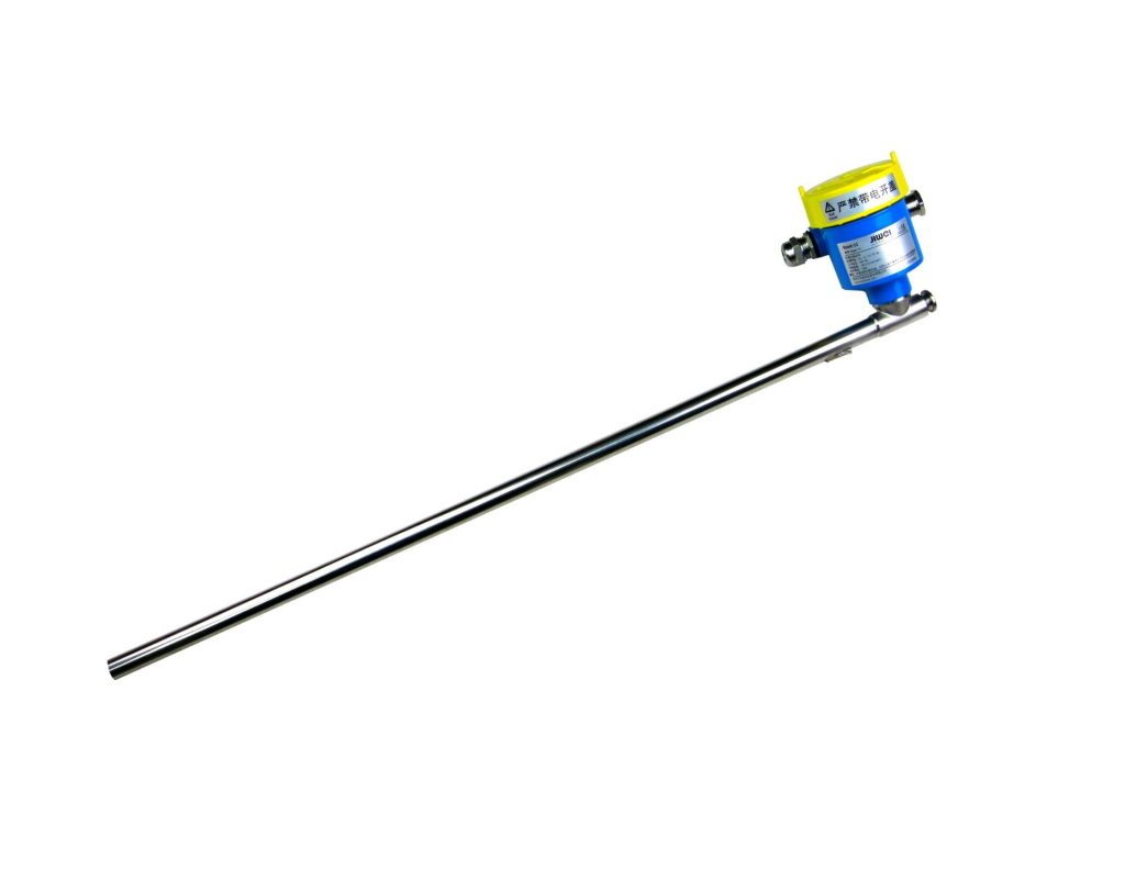
A remote transmitter is an instrument used to detect a field measurement and convert it into a standardized signal for transmission over a distance.
When installed with a magnetic level indicator, one of the most common designs is the reed switch transmitter. It is mounted externally along the measuring chamber and operates through magnetic coupling with the float inside the chamber.
As the process level rises or falls, the magnetic float moves with it. The external sensing device detects the float position and converts that position into a 4–20 mA current signal.
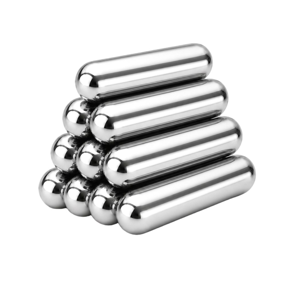
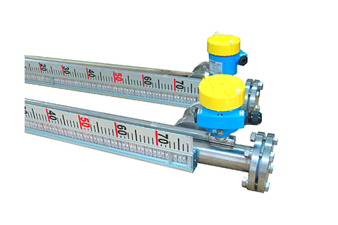
Jiwei’s Reed-11 and Reed-21S models are designed for use with the Flap-11 series magnetic level indicators. They enable the liquid level measured at the vessel to be transmitted to a control room for continuous monitoring, alarm management, and process control.
It is important to understand that this type of instrument is not normally an independent liquid level sensor. It relies on the magnetic float inside the level indicator to provide the position information required for signal conversion.
How Does It Work?
The operating principle can be divided into four stages:
- Liquid level movement
- Magnetic switching
- Resistance variation
- Signal conversion
1. The Liquid Level Moves the Magnetic Float
The measuring chamber of a magnetic level indicator is connected to the process vessel.
Based on the communicating-vessel principle, the liquid level inside the chamber follows the liquid level inside the tank. When the process level rises or falls, a float containing a permanent magnet moves up or down with the liquid surface.
The local indicator uses magnetic coupling to rotate a row of colored flaps or rollers. This creates a visible liquid level indication without requiring direct contact between the display mechanism and the process medium.
2. The Magnetic Field Activates Reed Switches
Inside the external transmitter tube, a series of reed switches and resistors is arranged along the measuring length.
When the float reaches a particular position, its magnetic field closes the nearby reed switch. Reed switches outside the active magnetic field remain open.
Different float positions therefore create different switch combinations within the internal resistor network.
3. Float Position Becomes a Resistance Signal
As the reed switches change state, the total resistance of the internal circuit changes.
The assembly can be understood as a magnetically controlled potentiometer. The float acts like a moving contact, and each liquid level position corresponds to a different resistance or voltage value.
This method provides a simple and robust way to convert mechanical float movement into an electrical measurement.
4. The Signal Is Converted to 4–20 mA
An electronic conversion module changes the resistance or voltage signal into a standardized 4–20 mA current output.
The current signal can then travel through field wiring to a PLC, DCS, panel meter, recorder, safety system, or other receiving device.
For example, in a measuring range of 0 to 3 meters:
- 4 mA may represent an empty vessel.
- 20 mA may represent a full-scale level of 3 meters.
- Intermediate current values correspond to intermediate liquid levels.
The control system calculates the actual level from the measured current.
Jiwei Reed series configurations can provide a conventional 4–20 mA output. Selected versions can also support HART communication over the same two-wire loop.
Why Is the 4–20 mA Signal Widely Used?
The 4–20 mA signal remains one of the most common analog transmission standards in industrial automation.
A current loop is relatively resistant to voltage drop and electrical interference. This makes it suitable for long cable runs and demanding industrial environments.
It is also compatible with a wide range of equipment, including:
- PLC analog input modules
- DCS systems
- Panel indicators
- Data recorders
- Signal isolators
- Intrinsic safety barriers
- Process controllers
Another important advantage is the use of a “live zero.”
A valid lower-range measurement is represented by 4 mA rather than 0 mA. If the loop current drops to zero, maintenance personnel can often identify a broken wire, power loss, or loop failure instead of confusing the fault with an empty tank.
Smart versions may superimpose HART digital communication on the analog current signal. This can support parameter setting, device identification, status monitoring, and diagnostic functions without replacing the existing two-wire loop.
Main Functions in an Industrial System
Remote Liquid Level Monitoring
Once the field signal reaches the control room, operators can view the tank level without physically visiting the vessel.
This is especially useful for:
- Outdoor storage tanks
- Elevated vessels
- Chemical processing equipment
- Hazardous locations
- Restricted-access areas
- Tanks located far from the control room
Remote monitoring can reduce manual inspection work and improve the speed at which operators respond to changing process conditions.
Automatic Process Control
The level signal can be used by a PLC or DCS to control pumps, inlet valves, outlet valves, dosing equipment, and other process devices.
For example, the control system may close a filling valve when the liquid reaches an upper setpoint. When the level drops below a lower setpoint, it may start a transfer pump or open a make-up valve.
This makes continuous level measurement an important part of automated filling, draining, batching, and material transfer systems.
Alarm and Interlock Functions
A continuous measurement signal allows the automation system to generate several alarm levels, such as:
- High-level alarm
- Low-level alarm
- High-high-level alarm
- Low-low-level alarm
In critical applications, the measurement may also form part of an interlock or shutdown strategy.
Typical risks that can be reduced include:
- Tank overflow
- Pump dry running
- Equipment overheating
- Material supply interruption
- Process instability
Where safety integrity is required, the selected instrument, complete measurement loop, diagnostics, installation method, and proof-testing procedures must all meet the project’s functional safety requirements.
Historical Data and Trend Analysis
Once the measurement enters a digital control system, it can be stored as historical process data.
Plant personnel can use liquid level trends to analyze:
- Material consumption
- Tank filling rates
- Batch cycles
- Production efficiency
- Process stability
- Unexpected level fluctuations
- Equipment operating conditions
Historical information can also support maintenance planning and process optimization.
Continuous Transmitter vs. Magnetic Level Switch
A continuous transmitter and a magnetic level switch may both be fitted to the same magnetic level indicator, but they perform different functions.
A transmitter provides a continuously changing signal across the full measuring range. The control system can determine the approximate liquid level at any moment.
A magnetic level switch provides a discrete on/off signal at a selected position. It can indicate that the liquid has reached a high or low alarm point, but it cannot display the complete movement between the bottom and top of the vessel.
The distinction is simple:
- A continuous measurement device answers: “How high is the liquid now?”
- A magnetic switch answers: “Has the liquid reached this point?”
Many industrial installations use both types of device.
The analog measurement supports continuous monitoring and process control, while separate switches provide independent alarms or interlocks. This arrangement can improve the reliability of the overall level monitoring system.
Typical Applications
Reed switch measurement technology is commonly used on tanks, vessels, columns, drums, separators, and process chambers equipped with magnetic level indicators.
Chemical and Petrochemical Industry
Typical measured liquids include:
- Oils
- Solvents
- Acidic liquids
- Alkaline liquids
- Chemical feedstocks
- Intermediate products
- Process additives
Water and Environmental Engineering
Applications may include:
- Clean-water tanks
- Wastewater basins
- Chemical dosing vessels
- Neutralization tanks
- Sludge treatment systems
- Water storage equipment
Power Generation
Power plants may use similar systems on:
- Water tanks
- Condensate equipment
- Demineralized water units
- Boiler auxiliary systems
- Cooling water vessels
- Process collection tanks
Food, Pharmaceutical, and New-Energy Projects
These industries may also use magnetic level measurement systems when the materials, process connections, cleaning requirements, and hygienic design meet the relevant project standards.
However, suitability should never be judged by the industry name alone.
The following process conditions must also be reviewed:
- Operating temperature
- Operating pressure
- Liquid density
- Viscosity
- Corrosiveness
- Crystallization tendency
- Presence of solids
- Hazardous-area classification
- Installation space
- Environmental exposure
Key Selection Factors
Measuring Range
The sensing length must match the actual measuring range of the magnetic level indicator.
If the sensing section is too short, part of the upper or lower vessel area may not be measured. If the zero point, full-scale point, or mounting position is incorrect, the output signal may not correspond to the actual liquid level.
For this reason, the measuring length is generally specified according to the vessel dimensions and project conditions.
The following information should normally be confirmed before ordering:
- Center-to-center distance
- Required measuring range
- Zero reference position
- Full-scale position
- Overall chamber length
- Nozzle arrangement
- Mounting direction
Resolution
The resolution of a reed switch design depends largely on the spacing between the internal switches.
Smaller spacing creates more measurement steps and improves position resolution. However, it also increases the number of internal components.
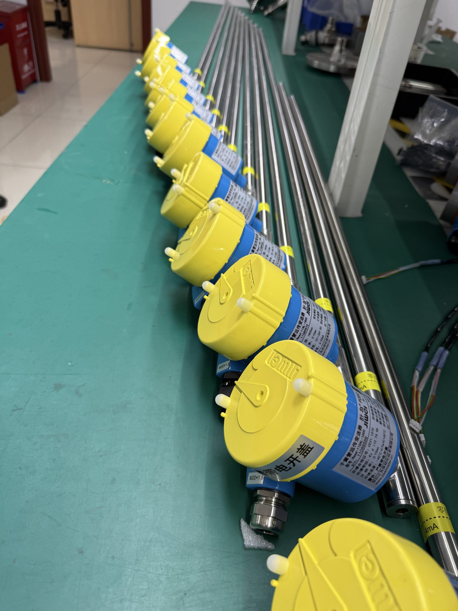
Jiwei Reed series options include ±5 mm and ±10 mm resolution configurations.
The appropriate selection depends on the tank height, control accuracy, and process requirements. A large storage vessel used for general inventory monitoring may not require the same resolution as a small process tank used for precise control.
Higher resolution is not automatically better. It should be selected according to the practical needs of the application.
Output and Communication
A 4–20 mA output is suitable for most conventional analog input systems.
HART communication may be useful when the project requires:
- Remote configuration
- Device identification
- Digital diagnostics
- Parameter verification
- Maintenance information
- Status monitoring
Before ordering, confirm the input type of the PLC or DCS, the loop power arrangement, the total load resistance, and whether an isolator or intrinsic safety barrier will be installed.
Power Supply
The Jiwei Reed-11 and Reed-21S series use a 10–36 V DC loop power supply.
The voltage available at the instrument must remain sufficient after accounting for:
- Cable resistance
- Safety barriers
- Signal isolators
- Receiving equipment
- Other voltage drops in the loop
Insufficient loop voltage may prevent the output from reaching full scale or may cause unstable operation.
Temperature Conditions
Process temperature and ambient temperature are different specifications and should be checked separately.
Process temperature refers to the temperature of the liquid or gas inside the vessel. Ambient temperature refers to the temperature surrounding the external electronics and housing.
Jiwei’s published product information lists a working temperature range of approximately −50 to 150°C and an ambient temperature range of approximately −20 to 50°C for the Reed series.
Final limits may vary according to the selected model, electronics, certification, mechanical arrangement, and installation method. Project-specific technical documents should therefore take priority.
Hazardous-Area Approval
Installations in petroleum, chemical, natural gas, and similar facilities may require explosion-proof or intrinsically safe equipment.
Jiwei Reed series configurations include explosion-protected options. The Reed-21S is also available in configurations intended for safety-related applications.
The selected protection method must match:
- Hazardous-area zone
- Gas group
- Temperature class
- Electrical connection
- Cable entry
- Safety barrier
- Wiring method
- Local regulations
A general “explosion-proof” description is not sufficient to confirm that a model is suitable for a specific hazardous area.
Enclosure Protection
Outdoor equipment may be exposed to rain, dust, washdown water, humidity, and condensation.
Jiwei Reed series product information lists enclosure protection ratings of IP66/IP67 for relevant configurations.
Even with a suitable enclosure rating, cable glands and unused entries must be correctly sealed. Poor cable entry installation can reduce the effective protection of the complete instrument.
Materials and Corrosion Resistance
Outdoor and corrosive environments can affect the service life of the transmitter housing, mounting hardware, cable glands, electrical connections, and supporting components.
The Jiwei Reed series uses a 304 stainless steel outer tube.
For strong chemical exposure, salt spray, washdown service, coastal environments, or special atmospheres, all wetted and non-wetted materials should be checked as part of the complete level measurement assembly.
Material selection should include the magnetic level indicator chamber, float, process connections, gaskets, bolts, external tube, cable gland, and mounting accessories.
Installation Guidelines
The remote transmitter should be mounted in the specified orientation along the outside of the magnetic level indicator chamber.
Its sensing range must align with the full travel of the internal magnetic float.
Incorrect height, reversed orientation, or poor alignment may cause:
- Zero-point offset
- Insufficient span
- Dead zones
- Incorrect signal direction
- Failure to reach 4 mA or 20 mA
- Disagreement between local and remote readings
For a two-wire system, the correct loop polarity must be observed.
Signal cables should be routed separately from high-voltage power cables whenever practical. Shielded cable may be useful in electrically noisy locations, and the shield should be grounded according to the project standard.
Before commissioning, check the following items:
- The magnetic float is installed in the correct direction.
- The measuring chamber is free of debris or blockage.
- The external sensing tube is securely fixed.
- The sensing range is correctly aligned with float travel.
- The configured zero and span match the actual measuring range.
- The output reaches the expected 4 mA and 20 mA values.
- Cable glands and seals are properly installed.
- Explosion-protection fittings meet the project requirements.
- Local indication and remote output move in the same direction.
A wet test or simulated float movement can be used to verify the complete measurement loop before the equipment enters normal service.
Maintenance and Troubleshooting
Reed switch transmitters do not use a complicated mechanical transmission system, so their routine maintenance requirements are generally limited.
Even so, periodic inspection is recommended.
Operators should compare the local magnetic display with the value shown in the control room. The signal should change steadily as the liquid level rises or falls.
A significant difference between the two readings may indicate:
- A stuck magnetic float
- Blockage inside the measuring chamber
- Weak magnetic coupling
- Movement of the external sensing tube
- Loose electrical terminals
- Damaged field wiring
- Incorrect calibration
- Insufficient loop voltage
If the output remains fixed near 4 mA or 20 mA, first confirm whether the tank is actually at the lower or upper measurement limit.
Then check:
- Loop power supply
- Wiring continuity
- Float movement
- Zero and span settings
- Sensing tube position
- Electronic conversion module
A zero-current reading often indicates a power or wiring problem.
An unstable reading may be caused by loose connections, inadequate supply voltage, electrical interference, severe vibration, damaged wiring, or intermittent reed switch operation.
Measurement loops used for alarms, shutdowns, or safety functions should be inspected, calibrated, and proof-tested according to the plant’s maintenance and functional safety procedures.
Frequently Asked Questions
Can the Device Operate as a Standalone Level Instrument?
A reed switch type unit normally works with a magnetic level indicator and its internal magnetic float.
It is not installed directly into the liquid like a submersible level sensor. Without the movement of the magnetic float, it cannot determine the process level.
Does a 4 mA Output Indicate a Fault?
Not necessarily.
In a standard 4–20 mA range, 4 mA usually represents the lower measurement limit. A reading close to 0 mA is more likely to indicate power loss, open wiring, or another loop failure.
The exact alarm current may also depend on the electronics and control system configuration.
Is Higher Resolution Always Better?
No.
Higher resolution may require more internal reed switches and other components, which can increase product complexity and cost.
The correct resolution should be selected according to:
- Measuring range
- Vessel height
- Required control accuracy
- Process stability
- Budget
- Actual application needs
Is It the Same as Every Type of Level Transmitter?
No.
The general term “level transmitter” also includes radar, ultrasonic, differential-pressure, displacer, capacitance, magnetostrictive, and submersible technologies.
The device discussed in this article is specifically designed to operate with a magnetic level indicator and magnetic float.
Can It Be Installed in a Hazardous Area?
Yes, provided that the selected model and the complete installation meet the actual hazardous-area requirements.
The approval, wiring method, safety barrier, cable gland, earthing arrangement, and installation practice must all comply with the project specification and applicable regulations.
Can a Magnetic Switch Be Used Instead?
A magnetic switch can be used when only a fixed-point alarm or control action is required.
However, it cannot replace a continuous measurement signal when the operator needs to know the actual level throughout the full measuring range.
For many applications, the two devices are used together.
Conclusion
A remote transmitter converts the position of a magnetic float into a standardized electrical output, allowing a locally indicated liquid level to be monitored from a control room.
When combined with a magnetic level indicator, it provides both direct visual indication and access to PLC, DCS, alarm, interlock, and data-recording functions.
This makes the system a practical solution for tanks and process vessels where operators require both local visibility and continuous remote monitoring.
Reliable operation depends on correct product selection. The measuring range, resolution, signal type, loop voltage, temperature limits, hazardous-area approval, enclosure protection, materials, and installation conditions should all be reviewed before purchase.
With proper matching, installation, and maintenance, a reed switch liquid level measurement system can provide a clear, robust, and automation-friendly solution for industrial process monitoring.

