
A radar level meter can provide accurate, stable, and low-maintenance level measurement—but only when it is installed and commissioned correctly. Many problems blamed on the instrument are actually caused by the mounting position, nozzle geometry, internal obstructions, incorrect tank parameters, poor cable routing, or an unsuitable false-echo map.
This radar level meter installation guide explains the practical steps required for reliable measurement in liquid tanks, process vessels, silos, hoppers, sumps, and open-air applications. It also reviews the most common installation mistakes, the symptoms they create, and the best corrective actions.
The main rule is simple: the radar sensor needs a clear, correctly aimed path from the antenna to the product surface. Vessel shape, internal fittings, process conditions, product properties, measuring range, and required response time should all be reviewed before selecting the mounting point.

How a Radar Level Meter Works
A non-contact radar level meter transmits electromagnetic signals toward the material surface. The signals reflect back to the antenna, and the instrument calculates the distance between its reference point and the measured surface. It then converts that distance into level, percentage, volume, or another process value.
Because the sensor measures from above without touching the product, radar technology is widely used for chemicals, oils, wastewater, powders, granules, cement, minerals, and other bulk solids. However, “non-contact” does not mean “installation-independent.” A strong reflection from a nozzle, ladder, agitator, support beam, filling stream, or vessel wall can compete with the true level echo.
Higher-frequency instruments, including many 80 GHz models, generally offer a narrower beam and stronger signal focusing. This can help the beam avoid obstacles and pass through smaller openings, although correct alignment and model-specific installation limits remain essential.
Before Installing the Radar Level Meter
Confirm that the measuring range covers the distance from the antenna reference point to the lowest level. The highest level must remain outside the sensor’s minimum measuring distance or near zone. Check that the process connection, antenna, gasket, and wetted materials are compatible with the product, pressure, temperature, cleaning method, and required approvals.
Inspect the housing, antenna, terminals, seals, and accessories for damage or contamination. Clean the mounting connection and verify that the flange or threaded socket is properly aligned. Outdoor installations should also be protected against rain, direct sun, flooding, lightning, and mechanical impact.
Create a simple vessel sketch showing the inlet, outlet, agitator, ladder, coils, supports, heating elements, spray devices, internal pipes, and expected product surface. This drawing is often more useful than selecting the easiest available nozzle.
Step-by-Step Radar Level Meter Installation
1. Select the Mounting Position
Choose a point where the radar beam can reach the product surface without crossing the filling stream or striking internal structures. Keep the sensor away from agitators, ladders, heating coils, reinforcing bars, limit switches, and large weld seams whenever possible.
Do not use one wall-clearance rule for every instrument. Beam angle varies by frequency, antenna type, and antenna size. Check the beam diameter across the full measuring range and make sure it remains clear at both high and low level.
2. Consider the Vessel Shape
Flat-roof tanks, domed tanks, spherical vessels, conical-bottom tanks, and silos produce different reflection patterns. Mounting in the geometric center of a dished or rounded roof can create multiple reflections. In some conical-bottom vessels, however, a central or carefully aimed position may improve measurement toward the lowest point.
The best position is application-specific. Review the complete vessel geometry before drilling a new opening or approving an existing nozzle.
3. Check the Nozzle
The nozzle is a common source of near-range false echoes. Its internal diameter, length, weld quality, and alignment must suit the selected antenna.
Avoid rough welds, burrs, corrosion, deposits, and internal steps. Do not recess an antenna deep inside a long, narrow nozzle unless that arrangement is permitted for the model. Where required, allow the antenna face to extend beyond the nozzle so the signal is not trapped or reflected by the connection.
4. Align the Antenna
For liquids, aim the antenna as close to perpendicular to the average surface as possible. An unnecessarily tilted sensor may send the strongest reflection away from the receiver.
For bulk solids, the surface slope changes during filling and discharge. Aim the beam toward a representative measuring point that remains visible throughout the operating cycle. An adjustable flange or aiming device is useful on tall silos and steep material cones.
5. Install and Seal the Connection
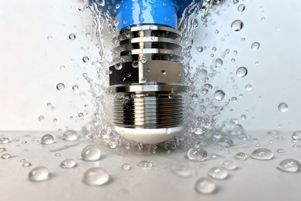
For flanged mounting, use the correct gasket and tighten bolts gradually in a cross pattern. Uneven tightening can tilt the sensor, damage the gasket, or distort a small flange.
For threaded mounting, use a sealing method compatible with the process and thread standard. Do not rotate or apply excessive torque through the electronics housing. Position the housing so the display, cable entries, and cover remain accessible.
6. Complete the Wiring
De-energize the circuit before wiring. Follow the terminal diagram for the selected 4–20 mA, HART, fieldbus, Modbus, relay, or other output.
Route instrument cables separately from high-voltage cables, variable-frequency-drive wiring, motors, and other noise sources. Use suitable shielded cable where required, follow the specified grounding method, tighten the cable gland, and close unused entries with approved plugs. In outdoor installations, form a downward cable loop so water cannot run toward the gland.
7. Configure and Verify the Measurement
Enter the correct tank height, empty distance, full distance, units, product type, response speed, output scaling, and alarm behavior. The measuring reference point must match the point defined by the instrument.
Compare the radar distance with an independent reference at one or more known levels. Review the echo curve instead of relying only on the displayed level. A clean echo profile makes it easier to identify nozzle reflections, vessel-wall echoes, buildup, or an incorrectly selected target.
Common Radar Level Meter Installation Mistakes and Solutions
Mistake 1: Installing Directly Above the Inlet
Problem: The filling stream creates turbulence, dust, splashing, buildup, or a strong moving reflection. The reading may jump during filling or track the inlet stream instead of the product surface.
Solution: Move the sensor away from the inlet path or redirect the filling stream. In a silo, consider how the material pile changes and choose a point that represents the level required for process control or inventory.
Mistake 2: Mounting Too Close to the Vessel Wall
Problem: The beam touches the wall, welds, buildup, stiffeners, or attached piping. The resulting echo may become stronger than the product echo, especially near empty.
Solution: Reposition the sensor or use a narrower-beam model. Confirm clearance through the entire measuring range. If relocation is impossible, optimize orientation and create a false-echo map under suitable process conditions.
Mistake 3: Mounting in the Center of a Domed Tank
Problem: Curved and symmetrical surfaces can focus indirect reflections back toward the antenna, creating multiple echoes or a false high reading.
Solution: Move the sensor away from the geometric center and verify the new position by checking the echo curve.
Mistake 4: Ignoring Internal Obstacles
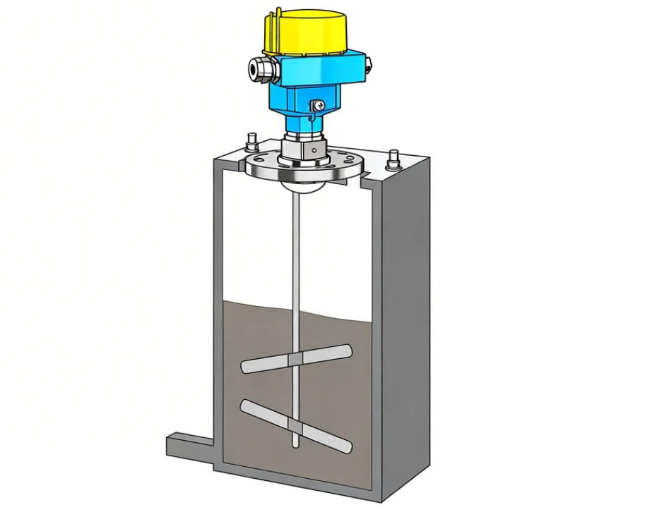
Problem: Agitator blades, ladders, coils, braces, pipes, and supports generate false echoes. A rotating agitator may cause regular spikes or cycling measurements.
Solution: Map the internals before selecting the mounting point. Aim the beam between obstacles. Where a structure cannot be avoided, consider changing the location, beam width, sensor orientation, or measurement technology.
Mistake 5: Using an Unsuitable Nozzle
Problem: A long, narrow, misaligned, or poorly welded nozzle produces a strong near-field reflection. The meter may show a fixed high level, lose the product echo, or become unreliable when condensation forms.
Solution: Shorten or enlarge the nozzle where practical, smooth internal welds, correct its alignment, or use an antenna designed for the connection. Software should not be used to hide poor mechanical geometry.
Mistake 6: Incorrect Sensor Alignment
Problem: The transmitted energy does not return efficiently. Liquids may show weak echoes, while solids may disappear from measurement as the material slope changes.
Solution: Use a level, adjustable flange, or aiming device. For liquids, aim toward the normal surface. For solids, check echo strength during filling and emptying and adjust toward the most representative area.
Mistake 7: Allowing Product into the Near Zone
Problem: The maximum level rises too close to the antenna, where the sensor cannot separate the surface reflection from antenna and nozzle effects.
Solution: Confirm the model-specific minimum measuring distance. Lower the maximum operating level, raise the mounting point, modify the nozzle, or select a sensor with a shorter near zone.
Mistake 8: Poor Cable Routing or Gland Sealing
Problem: The meter resets, communication drops out, the current output fluctuates, or moisture enters the housing.
Solution: Separate signal and power wiring, verify loop voltage under load, follow the correct shield and grounding method, tighten glands, seal unused entries, and add surge protection where appropriate.
Mistake 9: Entering Incorrect Empty and Full Values
Problem: The measured distance may be correct while the displayed level, percentage, or volume is wrong.
Solution: Confirm the reference point, tank height, zero point, full point, offset, and output scaling. Distinguish between “distance to product” and “product level.” For irregular tanks, verify the strapping or linearization table.
Mistake 10: Creating False Echo Suppression at the Wrong Level
Problem: If false-echo learning is performed while the product surface is inside the mapped range, the true level echo may be stored as interference. The instrument can then ignore the real surface in that region.
Solution: Perform false echo suppression only when the actual product distance is known and the level is below the obstructions being mapped. Update the map after sensor relocation, nozzle changes, new internals, or major buildup. Automatic false-echo functions can ignore vessel obstructions, but they still require correct process information.
Mistake 11: Ignoring Buildup and Condensation
Problem: Material on the antenna or nozzle gradually weakens the useful echo and increases near-range reflections. Foam, dense vapor, and dust may also reduce signal confidence in some applications.
Solution: Choose an antenna and mounting arrangement that minimize accumulation. Improve insulation or ventilation where condensation is the cause. Establish cleaning and inspection intervals based on the actual buildup rate.
Mistake 12: Skipping Final Validation
Problem: The meter appears to work at startup but fails near empty, near full, during agitation, or during rapid filling.
Solution: Test as much of the operating range as practical. Compare the reading with a reliable reference, review the echo curve, check output scaling, and confirm alarm behavior. Save the final parameters and echo profile as the commissioning baseline.
Quick Radar Level Meter Troubleshooting Guide
| Symptom | Likely Cause | Recommended Action |
|---|---|---|
| Fixed high reading | Nozzle or nearby obstacle echo | Inspect the nozzle, check antenna position, review the echo curve, and redo the false-echo map |
| Reading jumps during filling | Inlet stream, dust, or turbulence | Move the sensor, redirect the inlet, or adjust damping carefully |
| Correct distance but wrong level | Incorrect empty/full values or offset | Correct the reference point, tank height, and output scaling |
| Signal lost near empty | Beam reaches the wall or an internal structure | Re-aim or relocate the sensor |
| Signal lost near full | Product enters the near zone or antenna has buildup | Increase clearance and clean the antenna |
| Output changes when motors run | Electrical interference or grounding problem | Separate cables and check shielding, grounding, and power supply |
| Gradual performance decline | Condensation, coating, corrosion, or a loose connection | Inspect the antenna, seals, glands, terminals, and mounting hardware |
Installation Tips for Different Applications
For liquid tanks, prioritize a perpendicular view of a reasonably calm surface. Avoid inlet jets and strong vortex zones. In agitated vessels, mount the sensor away from the shaft and blade path.
For bulk-solid silos, account for the angle of repose, multiple filling points, ratholing, and asymmetrical discharge. Decide whether the measurement should represent average inventory, the highest pile, or a repeatable control point.
For corrosive or hygienic processes, verify compatibility with both the product and cleaning chemicals. Avoid crevices where residue can collect and confirm that the connection meets the required sanitary or corrosion-resistance standard.
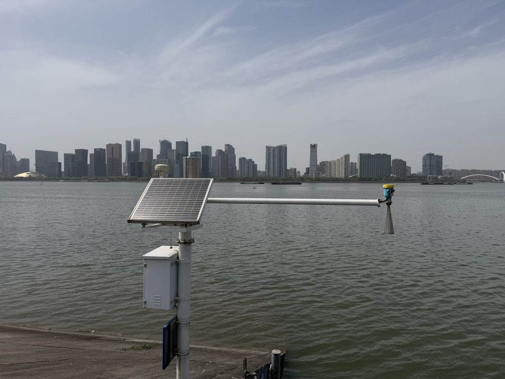
For outdoor installations, protect the housing and cable entries from water, UV exposure, icing, flooding, and lightning. Make the mounting structure rigid because movement of the bracket changes the measured distance.
Radar Level Meter Installation FAQ
How Far Should a Radar Level Meter Be from the Tank Wall?
There is no universal distance. Required clearance depends on beam angle, antenna design, measuring range, vessel shape, and expected buildup. Use the model’s beam diagram and keep the full beam path clear.
Can a Radar Level Meter Be Installed in the Center of a Tank?
Sometimes. Center mounting may work in certain flat-top or conical-bottom applications. It is often unsuitable on domed, rounded, or spherical roofs because multiple reflections can occur.
Should the Antenna Extend Below the Nozzle?
Many designs work best when the radiating surface is not recessed in a long nozzle, but the correct arrangement is model-specific. Follow the permitted nozzle diameter and length for the selected antenna.
When Should False Echo Suppression Be Performed?
Perform it after mechanical installation and basic configuration, when the actual product distance is known and the level is below the obstructions being mapped. Repeat it after relocation, nozzle modification, or major internal changes.
How Often Should the Meter Be Maintained?
Non-contact radar usually needs little routine maintenance, but the antenna, seals, cable glands, terminals, mounting hardware, and echo curve should still be inspected. The interval depends on dust, condensation, coating, corrosion, vibration, weather exposure, and process criticality.
Conclusion
Reliable radar level measurement begins with mechanical installation, not software. A clear beam path, suitable nozzle, correct antenna alignment, compatible process connection, disciplined wiring, accurate configuration, and properly executed false-echo suppression will prevent most commissioning problems.
When a radar level meter gives unstable or implausible readings, avoid changing multiple parameters at once. First inspect the physical installation, then verify the distance reading, tank geometry, echo curve, electrical supply, and suppression map.
By treating the radar level meter as part of the complete vessel and process—not as an isolated device—you can achieve more accurate level data, fewer false alarms, easier maintenance, and more dependable plant operation.

