
1. A Common Misconception: A Radar Level Transmitter Does Not Emit a Single “Line”
When discussing the installation of a radar level transmitter, one frequently hears statements such as:
“As long as there is no obstruction directly below the radar, the installation should be fine.”
Behind this statement is a very intuitive—but inaccurate—mental model: the radar signal is imagined as a thin “laser line” traveling vertically downward from the center of the antenna. Radar Beams
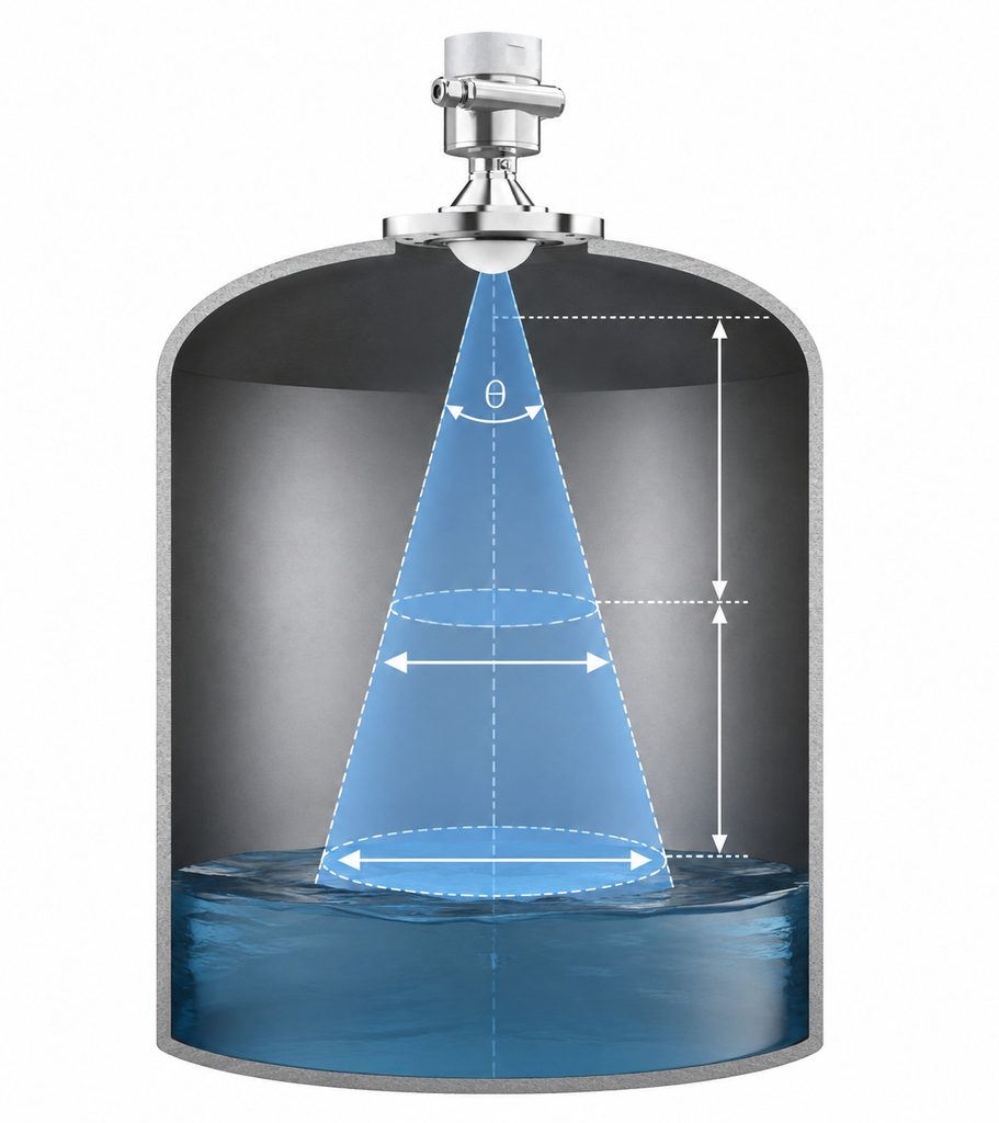
In reality, the electromagnetic energy transmitted by a radar level transmitter is not an infinitely thin line. It forms a directional radar beam with a measurable angular width and spatial energy distribution.
After leaving the antenna, electromagnetic energy propagates within a certain angular region. As the distance from the antenna increases, the lateral area covered by the radar beam generally becomes wider.
Therefore, the important engineering question is not simply:
Is there an obstruction directly on the radar centerline?
A more useful question is:
Does any obstruction enter the effective radar beam area?
Understanding this distinction is fundamental to the correct selection, installation, and commissioning of radar level transmitters for both liquids and bulk solids.
2. What Is the Beam Angle of a Radar Level Transmitter?
A radar antenna is directional.
In other words, the transmitted electromagnetic energy is not distributed equally in every direction. Most of the useful energy is concentrated toward the intended measurement direction.
One of the parameters used to describe this directional behavior is the beam angle.
For practical engineering purposes, the main radar measurement region is often illustrated as an expanding cone.
The antenna is located near the apex of this cone, while the radar energy propagates toward the surface of the measured product.
If the radar beam angle is θ and the propagation distance is L, the approximate beam diameter at that distance can be calculated using:
W ≈ 2 × L × tan(θ/2)
Where:
W = approximate beam width at the specified distance
L = distance from the radar antenna
θ = radar beam angle
Consider a simple example.
Suppose a radar level transmitter has a beam angle of approximately 8°.
At a measurement distance of 5 meters:
W ≈ 2 × 5 × tan(4°)
The result is approximately:
0.70 meters.
This means that at a distance of 5 meters from the antenna, the main radar beam may already cover an area approximately 700 mm in diameter.
Clearly, this is very different from an imaginary “laser line” only a few millimeters wide.
This is why an installation cannot automatically be considered interference-free simply because the vertical centerline below the radar antenna appears clear.
3. Why a Radar Beam Should Not Be Treated as a Perfect Solid Cone Either
Although engineering drawings often represent radar beams as cones, there is another misconception that should be avoided.
A real radar beam is not a solid cone with a perfectly sharp boundary.
The electromagnetic field transmitted by an antenna has a spatial energy distribution.
Energy is generally strongest around the antenna’s central axis and gradually decreases as the angular deviation from that axis increases.
The beam angle is therefore an engineering parameter used to describe the antenna radiation pattern.
The two lines commonly drawn to represent the beam boundary should not be interpreted as meaning:
“100% radar energy exists inside these lines, while zero radar energy exists immediately outside them.”
Real antenna radiation does not have such an abrupt boundary.
A more accurate interpretation is:
Most of the useful radar energy is concentrated within a defined angular region, while the energy gradually decreases away from the main axis.
Therefore, when engineers see a “beam angle” specification in a radar level transmitter datasheet, they should understand it as a parameter describing antenna directivity—not as an absolute geometric wall.
4. Main Lobes and Side Lobes: Why Objects Outside the Main Beam Can Still Matter
A deeper understanding of radar antennas requires two additional concepts:
Main lobe and side lobes.
The main lobe is the direction in which the antenna concentrates most of its transmitted energy. In radar level measurement, the main lobe is normally directed toward the product surface.
The transmitter expects the product surface to reflect part of this electromagnetic energy back toward the antenna.
However, practical antennas do not radiate energy exclusively within the main lobe.
Smaller amounts of energy may also exist in other directions. These secondary radiation regions are known as side lobes.
For this reason, the actual radiation pattern of a radar antenna is more complex than the simple triangular or conical shape normally shown in installation drawings.
This also explains why certain structures inside a tank can sometimes appear on an echo curve even when they are not directly on the antenna centerline.
Potential reflectors can include agitators, heating coils, internal pipes, tank reinforcement structures, ladders, support beams, filling pipes, nozzles, and other metallic internals.
However, there is an important distinction:
An object being capable of reflecting radar energy does not automatically mean that it will cause an incorrect level measurement.
Modern radar level transmitters analyze parameters such as echo amplitude, distance, signal stability, and signal behavior to identify the most likely product surface.
The complete echo environment therefore matters more than the position of a single object.
5. Why Does the Radar Beam Usually Become Wider with Distance?
This is one of the most important concepts in radar level transmitter installation.
Imagine a radar transmitter installed at the top of a 10-meter-high storage tank.
Close to the antenna, the lateral width of the main beam is relatively small.
Near the bottom of the tank, however, the beam has expanded considerably.
Therefore, whether an internal obstruction affects the measurement depends not only on its horizontal distance from the radar centerline but also on its vertical distance from the antenna.
Consider a pipe located 500 mm away from the radar centerline.
If that pipe is only one meter below the antenna, it may remain outside the main beam.
If the same pipe is located eight meters below the antenna, it may fall inside the main beam because the beam has become considerably wider at that distance.
This is why evaluating a radar installation requires more than asking:
“How many millimeters is the obstruction from the antenna centerline?”
You must also ask:
“How far below the radar antenna is the obstruction?”
For this reason, some radar manufacturers provide not only beam-angle specifications but also beam-width values at different measurement distances.
These values help engineers determine whether internal tank structures are likely to enter the main measurement region.
6. Why Do 80 GHz Radar Level Transmitters Emphasize a “Narrow Beam”?
In recent years, 80 GHz radar level transmitters have become widely used for industrial liquid and bulk-solid level measurement.
One of their commonly highlighted advantages is improved beam focusing.
However, an important technical distinction needs to be made.
It is not completely accurate to say:
“Higher frequency always means a narrower beam.”
From antenna theory, beam width is closely related to both the wavelength and the effective antenna aperture.
An 80 GHz radar has a shorter wavelength than a 26 GHz radar. With appropriate antenna dimensions and antenna design, this shorter wavelength makes it possible to achieve a relatively narrow beam with high directivity.
This can be particularly valuable in tanks containing complex internal structures.
Consider a vessel containing an agitator shaft, heating coils, filling pipes, and structural reinforcement.
A wide radar beam has a greater probability of illuminating these fixed internal objects.
A narrow-beam radar can concentrate more energy toward the intended target area, reducing the probability that certain internal structures will fall within the main measurement beam.
This is one reason why 80 GHz radar technology is frequently used for narrow vessels, small process connections, tanks with limited installation space, and vessels containing numerous internal structures.
However:
A narrow beam does not mean zero beam width.
An 80 GHz radar level transmitter is still not a laser.
Any real antenna has an antenna radiation pattern, a defined beam angle, and a beam width that must be considered over the full measurement distance.
7. Why Can Beam Angles Differ So Much Between Radar Level Transmitters?
When comparing different radar level transmitters, engineers may notice significant differences in beam angle.
Some radar instruments have beam angles of only a few degrees, while others may have beam angles exceeding ten degrees.
The reason is simple:
Beam angle is not determined solely by the fact that the instrument uses radar technology.
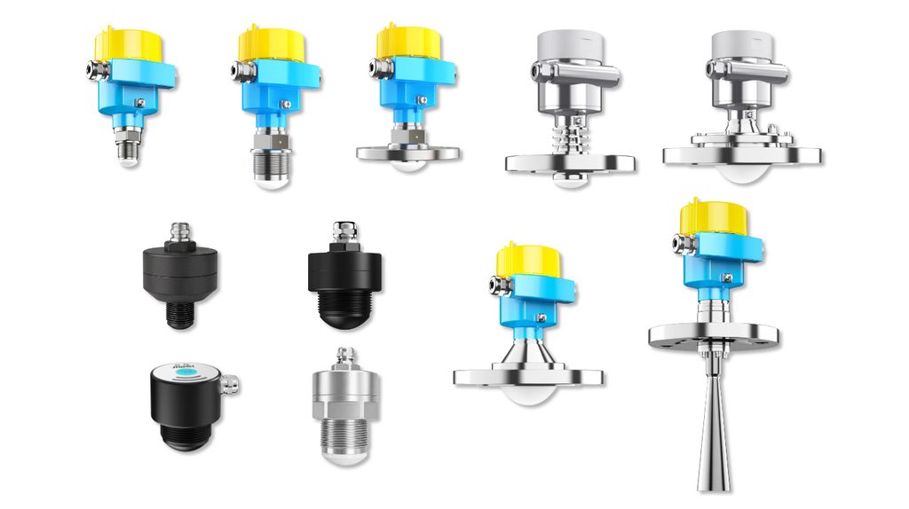
It depends on several interconnected parameters, including operating frequency, antenna size, antenna type, effective aperture, and overall antenna design.
Even within the same radar product family, changing the antenna size may significantly change the beam angle.
For this reason, it is technically incomplete to say:
“This is an 80 GHz radar, so its beam is very narrow.”
A more professional approach is to consult the datasheet for the exact transmitter configuration and determine:
What is the specified beam angle for this particular model and antenna?
That is the value that should be used for engineering evaluation.
8. Why Do Tank Walls, Pipes, and Agitators Produce False Echoes?
Radar level measurement relies on the propagation and reflection of electromagnetic waves.
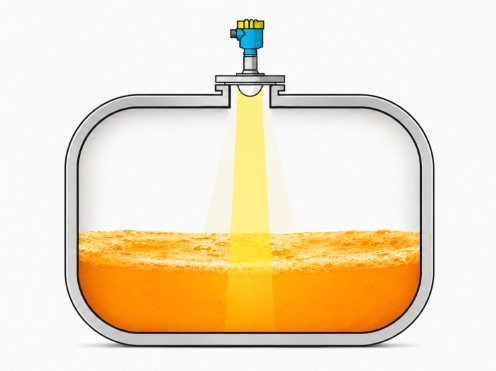
In a typical non-contact radar measurement, the antenna transmits a signal toward the product surface. Part of that energy is reflected back toward the radar antenna.
The distance can be represented in simplified form as:
D = c × t / 2
Where:
D = distance between the sensor and the reflecting surface
c = propagation velocity of the electromagnetic wave
t = round-trip signal travel time
The instrument then converts the measured distance into a level value using the configured tank geometry or reference height.
The challenge is that the product surface is not the only object inside the vessel capable of reflecting electromagnetic energy.
Metal pipes, tank walls, structural supports, heating coils, agitators, and other internal components can also produce strong reflections.
As a result, a radar level transmitter may receive multiple echoes rather than one single clean echo.
These echoes occur at different distances and with different amplitudes.
One of the key tasks of a modern radar level transmitter is therefore to identify which echo represents the actual product surface.
This means that interference immunity depends not only on antenna beam width but also on the transmitter’s dynamic range, signal-processing algorithms, echo tracking, and false-echo suppression capabilities.
9. What Does “Avoid Obstructions” Really Mean During Radar Installation?
Once we understand that a radar beam is not a single line, the logic behind installation becomes much clearer.
The correct approach is not simply to draw a vertical line downward from the center of the antenna and confirm that no object crosses that line.
A better engineering method is to use the specified beam angle of the selected radar level transmitter and estimate or draw the main beam region on the tank cross-section.
The engineer can then evaluate whether important internal structures enter that region.
Particular attention should be paid to structures such as agitators, filling pipes, manway edges, reinforcement structures, ladders, heating coils, support members, and other significant reflectors.
The minimum expected level should also be considered.
Why?
Because the greater the propagation distance, the wider the beam will generally become.
Therefore:
The lower section of a tall vessel can sometimes be more critical than the area immediately below the antenna.
This is especially important for tall tanks, narrow vessels, silos, and tanks containing extensive internal structures.
10. If the Radar Beam Reaches the Tank Wall, Will the Measurement Definitely Fail?
No.
This is another situation where absolute statements should be avoided.
If part of the radar beam reaches the tank wall, that does not automatically mean the transmitter will provide an incorrect measurement.
Measurement reliability depends on multiple factors, including the dielectric properties and reflectivity of the measured medium, tank-wall geometry, obstruction size, obstruction position, echo amplitude, multipath reflections, antenna directivity, signal-processing capability, and false-echo suppression algorithms.
Therefore, the presence of a structure within or near the beam should be treated as a potential measurement risk that needs to be evaluated, rather than an automatic pass/fail condition.
For difficult applications, one of the most valuable diagnostic tools is not simply the final level value displayed by the instrument.
It is the echo curve or echo profile.
By examining the echo curve, engineers can observe the product-surface echo, fixed interference echoes, and the relationship between different reflecting targets.
Echo-curve analysis is therefore an important part of radar level transmitter commissioning and troubleshooting.
11. When Selecting a Radar Level Transmitter, Do Not Look Only at Range and Accuracy
When selecting a radar level transmitter, users often begin with two questions:
“What is the maximum measuring range?”
and:
“What is the measurement accuracy?”
Both specifications are important.
However, for vessels with complicated internal geometry, another parameter can be equally important:
Beam Angle.
Beam angle deserves particular attention in narrow tanks, tall vessels, agitated process vessels, reactors containing internal piping, tanks where the installation nozzle is close to the wall, conical silos, powder silos, and small vessels with limited installation space.
In these applications, beam angle can directly affect installation flexibility and the probability of unwanted reflections.
A complete radar level transmitter selection process should therefore consider:
measurement range + medium characteristics + antenna design + beam angle + installation position + internal tank structures + process conditions.
Selecting a radar transmitter based only on “80 GHz” or “±1 mm accuracy” provides an incomplete picture of actual application performance.
12. Conclusion: Think of Radar as a Directional Measurement Region with Width and Energy Distribution
To understand radar level measurement correctly, it helps to abandon the idea of a single “laser line.”
A more accurate model is:
A radar antenna transmits a directional electromagnetic beam toward the target. This beam has a defined beam angle, a measurable lateral width, and a spatial energy distribution. As the propagation distance increases, the main beam coverage generally becomes wider.
Therefore, a clear radar centerline does not necessarily mean the entire measurement beam is free of obstructions.
An 80 GHz radar can provide excellent focusing and a narrow beam, but it is still not a zero-width ray.
Similarly, an obstruction entering the radar beam does not necessarily mean that measurement will fail. Its actual influence depends on its position, reflective characteristics, the strength of the product echo, and the transmitter’s signal-processing capabilities.
For engineers working with radar level measurement, the most useful question is therefore not:
“What single line is the radar measuring along?”
Instead, ask:
“Over the entire measurement distance, what area does the effective radar beam actually cover?”
Once this concept is understood, radar level transmitter installation, obstruction avoidance, false-echo analysis, and the advantages of narrow-beam 80 GHz radar become much easier to evaluate.
FAQ: Common Questions About Radar Level Transmitter Beams
1. Does a radar level transmitter emit a straight line?
No. A radar level transmitter emits directional electromagnetic energy with a defined beam width. The main measurement region is commonly described using a beam angle, and its lateral coverage generally increases with distance from the antenna.
2. Does an 80 GHz radar measure only one point like a laser?
No. An 80 GHz radar can achieve excellent beam focusing through its shorter wavelength and appropriate antenna design, but it still has a real beam angle and antenna radiation pattern. It should not be treated as a zero-width ray.
3. Is a smaller radar beam angle always better?
Not necessarily. A smaller beam angle is often advantageous in narrow vessels and tanks containing many internal structures. However, proper radar selection must also consider the measured medium, measurement distance, antenna type, installation conditions, process conditions, and required signal quality.
4. How do you calculate radar beam width at the bottom of a tank?
For a simplified geometric estimate, use:
W ≈ 2 × L × tan(θ/2)
where L is the distance from the antenna and θ is the beam angle.
For actual engineering design, however, the beam-width information provided by the manufacturer for the specific radar model and antenna configuration should take priority over a simplified calculation.
5. Will a pipe inside the radar beam always cause a false level reading?
No. A pipe may generate an unwanted reflection, but whether that reflection affects the final measurement depends on the pipe’s size and position, its reflective characteristics, the strength of the actual product echo, and the radar transmitter’s echo-recognition and false-echo suppression capabilities. For difficult applications, reviewing the echo curve is recommended.

