
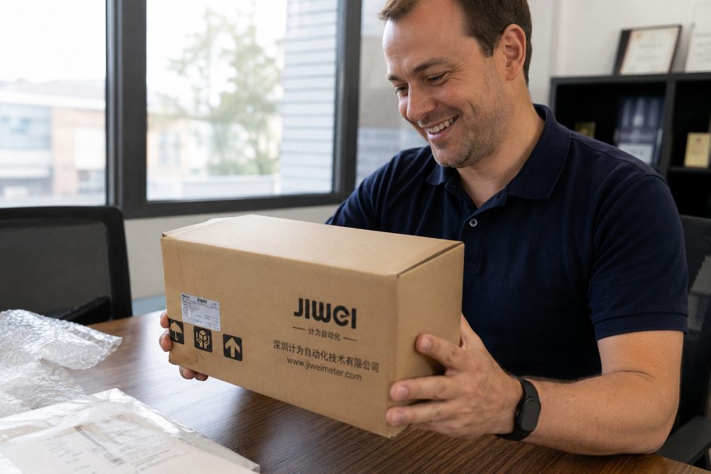
After receiving a JWrada-22 radar level transmitter, many users have the same questions: Can I power it on immediately? How can I check whether the instrument is working properly? Can I test it in an office or workshop before installing it on a tank or at the actual measurement site?
In fact, performing a basic test before installation is highly recommended.
By checking the appearance, power supply, display, distance measurement, output signal, and communication functions, you can confirm whether the radar level transmitter is operating normally before taking it to the field. This also helps engineers become familiar with the instrument’s measurement logic and can significantly reduce troubleshooting time during installation and commissioning.
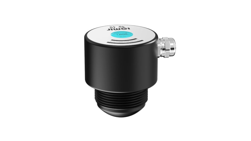
The JWrada-22 is a compact radar level transmitter based on 80 GHz FMCW technology. It features a narrow beam angle, non-contact measurement, a simple local display, and convenient commissioning options. With a maximum liquid level measuring range of up to 30 meters, it can be used in applications such as water management, rivers, open channels, wastewater treatment, water tanks, reservoirs, and general industrial liquid level measurement.
So, what should you test first after receiving a JWrada-22 radar level transmitter?
Here is a practical step-by-step guide.
1. Do Not Install It Immediately: Check the Model and Appearance First
When you receive the radar level transmitter, do not rush to install it at the measurement site.
Start with an inspection.
Check whether the packaging shows obvious signs of impact, crushing, water ingress, or other transportation damage. Then inspect the instrument itself, paying particular attention to the housing, display area, process connection, cable, and antenna section.
Next, verify the model and ordered configuration.
Depending on the selected configuration, the JWrada-22 may use a two-wire or four-wire power and signal arrangement. For example, a two-wire version may provide a 4–20 mA/HART output, while a four-wire version may use RS485/Modbus communication.
Therefore, before testing the device, make sure you know exactly which version you have received.
This may sound like a very basic step, but it is important.
A two-wire 4–20 mA radar level transmitter is not wired in the same way as a four-wire RS485 device. Powering the instrument without first confirming the wiring configuration can result in unsuccessful testing and, in some cases, incorrect wiring may affect normal operation.
2. Confirm the Power Requirements Before Powering On
Once you have confirmed that the instrument is physically undamaged and the model matches your order, you can proceed with the power-on test.
The JWrada-22 operates on a 12–30 V DC power supply. For workshop or bench testing, a suitable regulated DC power supply can be used. In many cases, a 24 V DC power supply is a convenient choice.
One point is especially important:
Never connect the wires based only on previous experience without first confirming the wiring definition.
Terminal and cable assignments can vary depending on the output configuration. Always follow the wiring information supplied with the specific instrument.
If you have a two-wire 4–20 mA version, remember that the power supply and current signal share the same loop. If you want to verify the 4–20 mA output during the test, you can connect a multimeter in series with the loop or connect the transmitter to an appropriate PLC/DCS analog input module.
If you have an RS485/Modbus version, connect the power supply correctly and then wire the RS485 communication lines according to the required communication settings. Parameters such as device address and baud rate should also be checked.
After confirming all wiring, switch on the power supply.
Under normal conditions, the transmitter should enter its operating state and the local display should show measurement information.
If nothing appears after power-up, do not immediately assume that the radar level transmitter is defective. Check the following first:
- Is the supply voltage correct?
- Is the polarity correct?
- Are any wires loose?
- Does the wiring method match the actual transmitter version?
- Can the power supply provide sufficient output?
Only after eliminating external power and wiring problems should you continue troubleshooting the instrument itself.
3. After Power-Up, Check the Distance First — Not the Level
This is one of the most important points when testing a radar level transmitter for the first time.
Some users power on the instrument, see a value that does not match their expected liquid level, and immediately assume the transmitter is inaccurate.
However, the fundamental measurement made by a radar level transmitter is the distance from the radar reference point to the target surface.
The JWrada-22 uses 80 GHz FMCW, or Frequency Modulated Continuous Wave, radar technology. The antenna transmits high-frequency electromagnetic waves toward the target. When these waves reach a liquid surface or another target, part of the signal is reflected back toward the antenna. The instrument analyzes the returned signal and calculates the distance between the radar and the target surface.
For this reason, before configuring complete tank parameters, the easiest way to test the instrument is not to verify the “level” value but to observe whether the measured “distance” changes correctly.
For example:
Position the radar vertically toward the floor.
Place it approximately 2 meters above the floor and observe the measured distance.
Then move the radar to approximately 1.5 meters above the floor.
Check the displayed distance again.
Under suitable test conditions, the displayed distance should change accordingly.
If the instrument can correctly follow the change in distance, this provides a good initial indication that the radar transmission, echo reception, signal processing, and basic measurement functions are operating properly.
4. The Simplest Test: Measure the Distance to a Wall or Floor
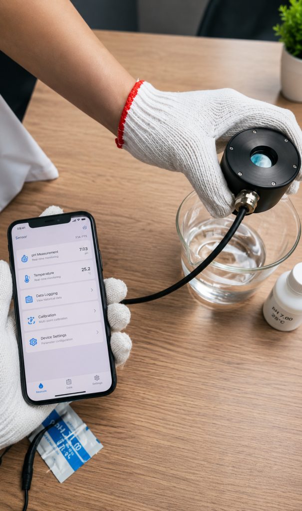
If you do not have a tank, water basin, or actual liquid level available, you can still perform a basic radar level transmitter test.
Find a relatively open area and securely position the JWrada-22 so that the antenna faces a large, flat target such as a wall or floor.
Why use a large, flat surface?
Radar measurement depends on receiving a useful reflected signal from the target. The purpose of the first test is not to reproduce every possible field condition. Instead, you want to create a simple and stable environment that makes the result easy to evaluate.
For example, you can perform the test as follows:
First, position the radar approximately 3 meters from the wall and record the displayed distance.
Next, reduce the distance to approximately 2 meters and record the result again.
Then reduce the distance to approximately 1 meter and observe the measurement.
A tape measure or laser distance meter can be used to check the actual distance and compare it with the radar reading.
Keep in mind that this type of office or workshop test is mainly intended to verify whether the instrument can detect a target correctly and whether its reading changes as the target distance changes.
It should not be treated as a substitute for a complete accuracy test under real operating conditions.
Actual measurement performance can also be affected by installation position, target dielectric properties, surrounding obstructions, parameter settings, and other application-specific factors.
5. Why You Should Not Use Your Hand as the Only Test Target
A common way to test a radar level transmitter is to place a hand under the antenna and move it up and down while watching the displayed value.
This can be useful as a very quick response check, but it is not recommended as the primary method for evaluating measurement accuracy.
The reason is simple.
A human hand has a relatively small surface area, and its position and angle constantly change. This does not provide a stable reflection target. In addition, nearby walls, tables, metal brackets, and other objects may produce additional echoes.
The problem becomes even more noticeable at longer test distances.
Therefore, when checking the basic ranging performance of the JWrada-22, it is better to use a target such as:
- A flat wall
- A floor
- A large metal plate
- A calm water surface
- Another large and stable reflective surface
These targets generally provide more meaningful and repeatable test results.
6. Pay Attention to the 6° Beam Angle During Testing
The JWrada-22 uses 80 GHz high-frequency radar technology with a beam angle of approximately 6°.
One important advantage of a narrow radar beam is that the transmitted energy is more concentrated. This can help reduce unwanted reflections in narrow spaces, small vessels, and applications where structural components are located near the measurement path.
However, a narrow beam does not mean that surrounding objects can be completely ignored.
As the measurement distance increases, the area covered by the radar beam also increases.
During testing and installation, try to prevent pipes, beams, brackets, internal structures, and other obstacles from entering the main measurement path.
The radar should also not be pointed at the target at an unnecessary angle.
For liquid level measurement, the antenna should normally point as vertically as possible toward the liquid surface. The same principle applies when testing against a wall or floor.
If the radar is significantly tilted, the strongest reflected energy may not return effectively to the antenna, which can affect measurement stability.
7. How to Simulate Real Liquid Level Changes
After completing a simple distance test against a wall or floor, you can perform a more realistic liquid level test using a water tank, bucket, or other suitable container.
If possible, choose a container with a relatively wide opening and a simple internal structure.
Secure the JWrada-22 above the container with the antenna pointing vertically toward the water surface.
Then change the water level in several stages.
For example:
Start with a low water level and record the measurement.
Add water to raise the level.
Wait until the surface becomes relatively calm, then record the new value.
Add more water and observe the measurement again.
An important relationship should be understood during this test:
When the liquid level rises, the distance between the radar and the liquid surface decreases. When the liquid level falls, the measured distance increases.
Once the zero point, full-scale point, and related parameters have been configured correctly, the transmitter can convert the measured distance into a corresponding level value.
For example, suppose the effective measuring height from the radar reference point to the bottom of a tank is 2 meters.
If the measured distance to the water surface is 1.5 meters, the corresponding liquid level is approximately 0.5 meters.
If the distance decreases to 1 meter, the liquid level is approximately 1 meter.
If the distance decreases further to 0.5 meters, the liquid level is approximately 1.5 meters.
Understanding the relationship between distance and level makes radar level transmitter commissioning much easier.
8. How to Test the Two-Wire 4–20 mA Output
If your JWrada-22 is configured with a 4–20 mA/HART output, it is recommended to test the analog signal after confirming that the local measurement is working correctly.
A multimeter can be connected in series with the current loop and set to the appropriate DC current measurement range.
Then change the target distance or simulate different liquid levels.
If the measuring range has been configured correctly, the output current should change accordingly as the measured level changes.
In a typical industrial application, 4–20 mA represents the configured measurement range. For example:
A low liquid level may correspond to 4 mA.
A high liquid level may correspond to 20 mA.
Suppose a 0–2 meter level range is configured to correspond to 4–20 mA. When the liquid level is around the midpoint of the range, the output current should also be approximately around the midpoint of the current range.
This type of test allows you to verify three important functions:
- Whether the radar detects the target correctly
- Whether the internal measurement value is correct
- Whether the 4–20 mA output follows the measurement value properly
If the local display is correct but the PLC reading is incorrect, troubleshooting can then focus on loop wiring, the analog input module, range scaling, or control system configuration rather than immediately suspecting the radar measurement itself.
9. How to Test the RS485/Modbus Version
If you are using an RS485/Modbus version, the testing procedure is slightly different.
First, verify that the radar itself is producing a stable measurement.
Then connect the RS485 communication interface to a compatible device such as a PLC, gateway, or USB-to-RS485 converter.
Configure the communication parameters according to the instrument settings and attempt to read the relevant measurement data.
If the local display is operating normally but the host system cannot receive data, check:
- Whether the A/B communication lines are connected correctly
- Whether the device address matches
- Whether the baud rate matches
- Whether other communication parameters are consistent
- Whether the correct registers are being read
- Whether all cable connections are secure
During industrial commissioning, it is useful to verify “measurement” and “communication” separately.
First confirm that the radar itself can measure the target reliably. Then test the RS485/Modbus communication.
This approach makes troubleshooting much more efficient.
10. Test the Bluetooth Function Before Installation
The JWrada-22 supports Bluetooth-based wireless commissioning, so it is a good idea to verify the wireless connection and parameter access before installing the instrument above a channel, tank, reservoir, or other hard-to-reach location.
The reason is practical.
Troubleshooting communication and parameter settings is easy when the instrument is sitting on a workbench. Once it has been installed several meters above the ground or in a difficult location, repeated physical access can require significantly more time and effort.
Testing the wireless commissioning function before installation can therefore save considerable work later.
After connecting, you can check measurement information and relevant parameters and complete basic configuration according to the requirements of the application.
For installations where direct physical access to the transmitter will be difficult, wireless commissioning can be particularly useful.
11. The Reading Is Fluctuating — Does That Mean the Radar Is Faulty?
Not necessarily.
Radar level measurement is based on reflected signals, which means the surrounding test environment can directly affect the echoes received by the instrument.
During an office or workshop test, nearby objects may include:
- Tables
- Chairs
- Walls
- Metal brackets
- Pipes
- Equipment housings
- Moving people
All of these objects can potentially generate reflections.
If the target is too small, the radar is not properly aligned, or there are too many objects in the test area, the displayed measurement may fluctuate.
The JWrada-22 uses intelligent echo processing to help identify false echoes, separate multiple echoes, and track the target. However, a suitable installation and test environment remains important for obtaining stable measurements.
Therefore, if the measurement fluctuates during a bench test, do not immediately conclude that the radar level transmitter is defective.
Move the instrument to a more open area and repeat the test using a large, stable target.
If the reading becomes stable after improving the test environment, the earlier fluctuation was likely related to the test conditions.
12. What Should Be Checked Before Final Installation?
After completing the basic tests, perform a final check before installing the JWrada-22 at the actual measurement site.
Confirm the following:
- The instrument powers on normally.
- The display and basic distance measurement are functioning correctly.
- The measured value responds correctly when the actual target distance changes.
- The 4–20 mA/HART or RS485/Modbus output works correctly according to the selected version.
- Bluetooth commissioning and parameter access are functioning normally.
- Basic parameters such as range, zero point, and full-scale point match the application.
- Pipes, beams, brackets, and other obvious obstructions will not interfere with the main radar measurement path.
Completing these checks before installation can significantly reduce unnecessary field troubleshooting and rework.
13. Where Can the JWrada-22 Radar Level Transmitter Be Used?
The JWrada-22 is a compact 80 GHz radar level transmitter with a maximum liquid level measurement range of up to 30 meters, measurement accuracy of up to ±1 mm, and a beam angle of approximately 6°.
It is suitable for water-related applications as well as relatively straightforward industrial liquid level measurement.
Typical applications include river level monitoring, open channel level measurement, wastewater treatment, reservoirs, sluice stations, municipal drainage and flood monitoring systems, industrial tanks, water basins, and small vessels.
Because radar provides non-contact measurement, the sensor does not need to be immersed directly in the liquid. In many water level applications, this can help reduce maintenance issues associated with direct contact between the sensor and the measured medium.
The narrow beam provided by 80 GHz radar technology can also be advantageous in smaller vessels or applications with limited installation space.
14. What Should You Test First After Receiving a JWrada-22?
The complete testing procedure can be summarized in one simple sequence:
Inspect first, then power on. Test distance before level. Check the local measurement before testing output and communication. Once the basic functions are confirmed, install the instrument at the actual site.
Avoid installing the radar level transmitter immediately after taking it out of the box.
This is particularly important when the installation point is high, construction conditions are complicated, or the transmitter needs to be integrated into a PLC or DCS system.
Completing basic tests in an office or workshop can save a significant amount of commissioning time later.
For first-time JWrada-22 users, the easiest initial test is straightforward.
Find an open area, secure the radar, and point it vertically toward a wall or floor. Connect the correct 12–30 V DC power supply and observe the measured distance. Then change the distance between the radar and the target.
If the displayed value follows the actual distance change consistently, the basic ranging function has been successfully verified.
After that, continue testing the 4–20 mA/HART output, RS485/Modbus communication, Bluetooth commissioning, and actual water level changes according to the specific transmitter configuration.
Testing each function from simple to complex is far more efficient than beginning troubleshooting only after the instrument has been installed in a real industrial environment.
Conclusion
Testing a JWrada-22 radar level transmitter after delivery does not need to be complicated. The key is to follow the correct sequence.
Start by checking the model and physical condition. Confirm the power supply and wiring configuration before powering on. Then verify basic distance measurement by changing the distance to a wall, floor, or water surface. After that, test the 4–20 mA/HART or RS485/Modbus output according to the transmitter version, followed by Bluetooth communication and final parameter verification.
It is important to remember that a bench test is primarily intended to confirm basic operation, measurement response, signal output, and communication. It does not completely replace testing under actual process conditions.
The long-term performance of any radar level transmitter also depends on installation position, target surface characteristics, surrounding obstructions, measurement range configuration, and actual operating conditions.
For engineers and maintenance personnel, spending a few minutes performing a structured test before installation can help identify wiring, configuration, and installation issues before they become field problems.
Test the radar in a simple environment first, understand how it responds, and then install it in the more complex real-world application. This is one of the most efficient ways to commission a JWrada-22 radar level transmitter.

