
1. Project Background: Why Do Machine Tool Hydraulic Oil Tanks Need Reliable Level Monitoring?
Hydraulic systems are widely used in CNC lathes, machining centers, grinding machines, boring and milling machines, and various automated manufacturing systems. They perform essential functions such as workpiece clamping and releasing, tool changing, spindle control, worktable movement, and the operation of auxiliary actuators. Float Level Transmitter
The stable operation of a hydraulic system depends heavily on hydraulic oil level, temperature, cleanliness, and operating pressure.
A machining company operates multiple CNC machines in its production workshop, with each machine equipped with an independent hydraulic power unit. During continuous operation, the hydraulic oil level may gradually decrease because of pipeline leakage, seal wear, equipment maintenance, or normal oil loss.
When the oil level becomes too low, the suction port of the hydraulic pump may draw in air. This can cause pressure fluctuations, increased operating noise, unstable actuator movement, and other hydraulic system problems. In more serious situations, insufficient oil may affect the lubrication and cooling of the hydraulic pump, increasing the risk of equipment failure.

Previously, the company mainly relied on operators to visually inspect the oil level through a sight glass or check the hydraulic oil tank during scheduled maintenance.
Although this approach is simple, it cannot provide continuous real-time oil level monitoring. As the number of machine tools increased, manual inspection became more time-consuming. More importantly, abnormal oil levels could only be discovered during inspections, making it difficult to implement effective preventive maintenance.
The company therefore wanted to add a reliable level monitoring system to its existing machine tool hydraulic oil tanks. The required instrument had to be structurally simple, stable during long-term operation, and capable of transmitting the oil level signal directly to the machine PLC.
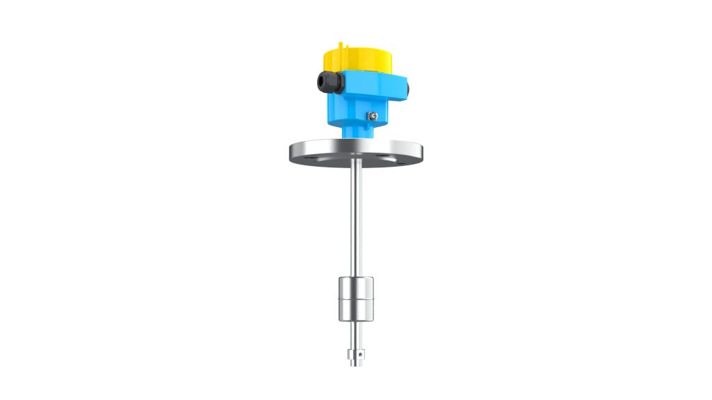
After evaluating the hydraulic oil characteristics, tank dimensions, installation space, and control system interface, the Float-11A standard float level transmitter was selected for continuous hydraulic oil level measurement.
2. What Are the Challenges of Hydraulic Oil Level Measurement in Machine Tools?
Compared with ordinary water storage tanks, machine tool hydraulic oil tanks are relatively small. However, they often impose higher requirements on level measurement reliability and installation adaptability.
The first challenge is mechanical vibration.
Machine tools generate a certain amount of vibration during operation. At the same time, the hydraulic pump and returning oil can cause minor fluctuations on the oil surface. If the level measuring instrument has a complicated mechanical structure or is easily affected by vibration, measurement stability may deteriorate after long-term operation.
The second consideration is the physical property of hydraulic oil.
Hydraulic oils have a certain viscosity, and their density varies depending on the oil type and grade. Since a float level transmitter operates according to the buoyancy principle, the density of the measured medium must be considered when selecting the float. The float must have sufficient buoyancy to follow changes in the liquid surface accurately.
Installation space is another important factor.
Machine tool hydraulic power units are often installed inside the machine enclosure or in a compact area beside the machine. Space around the oil tank may be limited. Therefore, the level transmitter should match the dimensions of the tank while still allowing convenient installation, electrical wiring, inspection, and future maintenance.
In addition, the customer wanted the hydraulic oil level signal to be directly integrated into the PLC control system.
When the oil level falls below a predefined threshold, the system should automatically generate a low-level alarm on the operator interface, allowing maintenance personnel to inspect the machine and refill hydraulic oil in time.
For this reason, continuous level measurement is more suitable for this application than a simple point-level switch that only provides an ON/OFF signal.
3. Why Use a Float Level Transmitter for Hydraulic Oil Tanks?
A float level transmitter is a continuous liquid level measuring instrument based on the buoyancy principle.
As the hydraulic oil level rises or falls, the float moves vertically with the liquid surface. A magnetic element inside the float interacts with reed switches installed inside the guide rod. As the float position changes, the internal resistance of the sensing circuit changes accordingly.
The transmitter then converts this change into a standard 4–20 mA DC output signal, enabling remote level indication, monitoring, and control.
This measuring principle offers several advantages for machine tool hydraulic oil tank applications.
Simple and Direct Measuring Principle
The float follows the actual liquid surface directly. No complicated calculation or sophisticated commissioning procedure is required.
For hydraulic oil tanks with relatively stable operating conditions, this principle provides a practical and reliable method of continuous liquid level measurement.
Continuous 4–20 mA Level Output
Unlike a point-level switch, a float level transmitter provides continuous level information.
The standard 4–20 mA output can be connected to a PLC, DCS, digital indicator, data acquisition system, or other industrial control equipment.
Operators can therefore monitor the actual oil level continuously rather than only receiving an alarm after the oil reaches a specific point.
Different alarm thresholds, such as low-level and low-low-level alarms, can also be configured in the PLC according to machine protection requirements.
Simple Installation
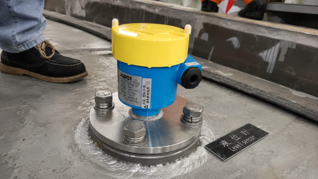
For hydraulic tanks with a suitable top opening or tanks that can be slightly modified, the float level transmitter can be vertically installed from the top of the tank.
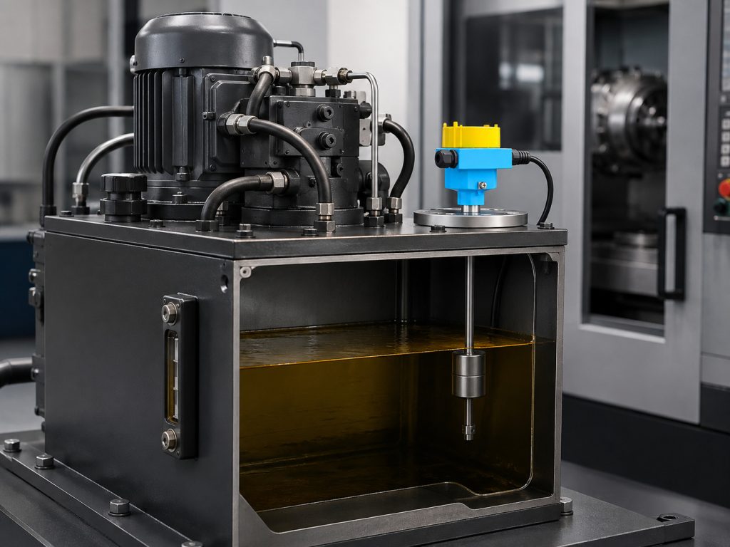
The guide rod extends downward into the hydraulic oil, while the float moves freely along the rod.
This installation method occupies relatively little external space, which is an important advantage for compact machine tool hydraulic units.
Suitable for Long-Term Operation
Machine tools are normally expected to maintain a high operating availability.
Level instruments used on these machines should therefore require as little routine maintenance as possible.
A float level transmitter using a magnetic coupling and reed-switch sensing principle avoids complicated mechanical transmission mechanisms, helping reduce maintenance requirements during long-term operation.
4. Float-11A Float Level Transmitter Selection
After evaluating the properties of the hydraulic oil and the structure of the oil tank, the Float-11A standard float level transmitter was selected for the application.
The wetted parts of the instrument are available in 304 or 316L stainless steel.
The measuring range is 300 to 6000 mm, while the required minimum medium density is 0.5 g/cm³.
The process temperature range is -20 to 120°C.
A standard 4–20 mA output signal is provided, with an operating power supply of 18–36 V DC.
Measurement accuracy options include ±5 mm and ±10 mm, while the enclosure protection rating can reach IP66/IP67.
For commonly used mineral-based hydraulic oils, the transmitter can be selected after confirming that the oil density, operating temperature, and material compatibility meet the instrument requirements.
The required guide rod length and measuring range are then determined according to the actual dimensions of the hydraulic oil tank.
In this application, the hydraulic oil tank operates under atmospheric pressure and the normal oil temperature remains within the allowable operating range of the transmitter.
Therefore, the most important selection factors are the measuring range, float specification, process connection, and output signal.
Determining the Correct Measuring Range
The measuring range should not simply be selected according to the total height of the oil tank.
Several factors should be considered together, including:
- Normal maximum oil level
- Minimum allowable operating level
- Position of the hydraulic pump suction port
- Internal tank structures
- Top installation clearance
- Required alarm thresholds
This allows the selected transmitter to cover the actual working level range while preventing the float or guide rod from interfering with internal pipes, filters, baffles, or other components.
Since the machine PLC was already equipped with an analog input module, a 4–20 mA output was selected.
The transmitter could therefore be connected directly to the control system without requiring additional complicated signal conversion equipment.
5. Installation of the Float Level Transmitter on the Hydraulic Oil Tank
The float level transmitter was installed vertically on the top of the hydraulic oil tank, allowing the float to move freely up and down along the guide rod.
Before installation, the internal structure of the tank was carefully checked.
The installation position had to remain clear of return pipes, suction pipes, filters, tank partitions, reinforcement structures, and any other components that could obstruct the movement of the float.
Special attention was paid to the hydraulic oil return line.
Installing the level transmitter directly beside a high-flow return outlet may expose the float to excessive turbulence and local liquid surface fluctuations. This could cause unnecessary variation in the measured level.
The final installation position was therefore selected away from the main return flow, in an area where the hydraulic oil surface remained relatively stable.
A suitable process connection was used according to the tank design to ensure secure installation.
After mounting, the maintenance team manually checked the complete travel of the float to confirm that it could move smoothly throughout the measuring range without sticking, collision, or mechanical interference.
The power supply and 4–20 mA output wires were then connected to the analog input module of the machine PLC.
The PLC program converted the analog signal into the corresponding hydraulic oil level or level percentage according to the actual measuring range.
After commissioning, operators no longer needed to open the machine enclosure or manually inspect the tank sight glass every time they wanted to know the oil level.
The current hydraulic oil level could be displayed directly on the machine HMI.
6. PLC Low-Level Alarm for Active Hydraulic System Protection
After the float level transmitter was commissioned, the company configured several hydraulic oil level zones in the PLC control program, including a normal operating range, a low-level warning range, and a low-low-level alarm range.
When the hydraulic oil level remains within the normal range, the machine operates according to the standard production sequence.
When the oil level falls to the low-level warning threshold, a warning message appears on the HMI.
Maintenance personnel can then inspect the oil tank, hydraulic pipelines, fittings, and sealing components. Hydraulic oil can be added if necessary.
If the level continues to decrease and reaches the lower protection threshold, additional control measures can be implemented according to the machine’s operating requirements.
These measures may include an audible and visual alarm, preventing the start of the next machining cycle, or activating another predefined machine interlock.
The purpose is to reduce the possibility of the hydraulic pump continuing to operate when the oil level is critically low.
Compared with traditional manual inspection, the major improvement is not simply that operators can “see the oil level.”
More importantly, hydraulic oil level becomes part of the machine’s automatic monitoring and protection system.
Maintenance personnel can identify abnormal oil loss earlier and use level changes as an additional indication of potential leakage.
For example, if the hydraulic oil level of one machine decreases noticeably within a relatively short period, personnel can inspect hydraulic pipes, joints, cylinders, and seals before the problem develops into a pressure failure or causes machine downtime.
7. Results of the Hydraulic Oil Level Monitoring Upgrade
After the level monitoring system was implemented, hydraulic oil tank management changed from periodic manual observation to a combination of continuous monitoring and routine inspection.
The first improvement was better level visibility.
Operators could check the current hydraulic oil level directly from the machine control interface without frequently opening covers or locating the oil sight glass.
The second improvement was earlier warning of insufficient hydraulic oil.
By configuring a low-level alarm, the maintenance team could receive notification before the oil reached a potentially critical level.
This provided additional time for inspection, oil replenishment, and troubleshooting.
Another benefit was the availability of a continuous 4–20 mA level signal for future digitalization projects.
If the company later connects the machines to a MES, equipment management platform, SCADA system, or centralized data acquisition system, hydraulic oil level data can be collected together with other machine operating parameters.
The company could then monitor hydraulic oil levels across multiple CNC machines from a centralized platform and establish maintenance strategies based on machine operating hours and oil consumption trends.
For workshops operating multiple CNC machines in batch production, this type of modification does not require major changes to the hydraulic system itself.
However, it significantly improves the visibility of hydraulic tank conditions and provides useful data for preventive equipment maintenance.
8. What Should Be Considered When Using a Float Level Transmitter in a Hydraulic Oil Tank?
Although a float level transmitter has a relatively simple structure, correct selection and installation are still essential for reliable operation.
Confirm Hydraulic Oil Density
The Float-11A is suitable for media with a density of at least 0.5 g/cm³.
The density of the actual hydraulic oil should therefore be checked during instrument selection, and the appropriate float configuration should be selected accordingly.
Sufficient buoyancy is essential for the float to follow the liquid surface accurately.
Check for Internal Mechanical Interference
The complete movement path of the float must remain unobstructed.
The float and guide rod should not interfere with suction pipes, return pipes, filters, reinforcement structures, baffles, or other components inside the hydraulic tank.
This should be checked before drilling or preparing the process connection.
Avoid Areas with Severe Surface Turbulence
The transmitter should preferably be installed away from high-flow return outlets.
Continuous turbulence near a hydraulic return pipe can cause local oil surface fluctuations and make the measured level less stable.
When installation space permits, choosing a calmer area of the tank helps improve measurement consistency.
Select the Measuring Range According to the Effective Oil Level
The total tank height is not the only factor that determines the correct measuring range.
The minimum safe operating level is especially important.
The hydraulic pump suction inlet should normally remain sufficiently submerged to prevent air from being drawn into the system.
Therefore, the position of the pump suction port should be considered when establishing the low-level and low-low-level alarm thresholds.
Include the Level Transmitter in Routine Maintenance
During scheduled machine maintenance, technicians can also check whether the float moves freely, electrical connections remain secure, and excessive sludge or deposits have accumulated on the guide rod.
These simple inspections help maintain stable level measurement over long-term operation.
9. Conclusion
The hydraulic system may be an auxiliary system on a CNC machine tool, but the hydraulic oil level has a direct impact on the reliable operation of the hydraulic pump, cylinders, valves, and other actuators.
Traditional visual oil level inspection can meet basic maintenance requirements, but it cannot provide the continuous monitoring, automatic alarms, and preventive maintenance functions increasingly required by modern manufacturing facilities.
The Float-11A float level transmitter follows changes in the hydraulic oil surface and converts the liquid level into a standard 4–20 mA output signal.
This signal can be connected directly to a machine PLC to provide real-time oil level indication, low-level alarms, and, where required, equipment interlock protection.
With 304 or 316L stainless steel wetted parts, a measuring range of 300–6000 mm, and an IP66/IP67 enclosure protection rating, the transmitter can be configured for hydraulic oil tanks of different sizes and installation conditions.
For CNC lathes, machining centers, grinding machines, automated machine tools, and other equipment using hydraulic power units, installing a suitable float level transmitter does more than answer the basic question of how much oil remains in the tank.
More importantly, it integrates hydraulic oil level into the machine monitoring and maintenance system.
By changing hydraulic oil management from passive manual inspection to continuous monitoring and early warning, machine operators and maintenance teams can identify abnormal conditions sooner, reduce the risk associated with insufficient oil levels, and provide a more reliable foundation for stable and continuous machine operation.

