
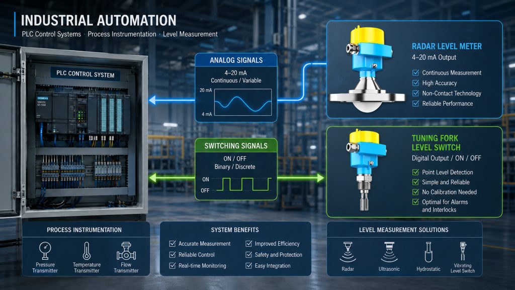
In industrial automation, PLC control systems, process instrumentation, and level measurement, two terms appear frequently: analog signals and switching signals.
For example, a radar level meter may transmit a 4–20 mA analog signal, while a level switch may provide a relay switching output. PLC systems also use different types of I/O modules, commonly identified as AI, AO, DI, and DO.
For engineers or technicians who are new to industrial instrumentation, these terms can sometimes be confusing.
What is the difference between an analog signal and a switching signal? Why is 4–20 mA considered an analog signal? Why is a relay output considered a switching signal? And when should you choose a continuous level meter instead of a level switch?
The easiest way to understand the difference is to remember one simple rule:
An analog signal tells the control system “how much,” while a switching signal tells the control system “whether or not.”
This article explains analog signals and switching signals in detail, with examples from industrial automation and level measurement applications using Jiwei’s level measurement instruments.
1. What Is an Analog Signal?
An analog signal is a signal that can vary continuously within a specified range.
Many physical variables in everyday life and industrial processes are continuous by nature. Typical examples include:
- Temperature
- Liquid level
- Pressure
- Flow rate
- Weight
- Speed
Consider a storage tank that is 10 meters high.
The liquid level inside the tank may be 1.2 m, 2.5 m, 6.38 m, or 9.1 m. The level is not limited to only two states such as “liquid present” or “liquid absent.”
If an operator needs to know the exact liquid level in real time, the measurement system must continuously detect and transmit the changing level value.
This is a typical analog measurement application.
Common analog signals used in industrial automation include:
- 4–20 mA current signal
- 0–10 V voltage signal
- 0–5 V voltage signal
- 1–5 V voltage signal
Among these, 4–20 mA is one of the most widely used analog signal standards in process automation and industrial instrumentation.
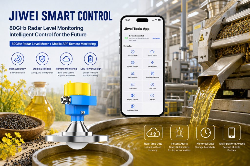
For example, the Jiwei JWrada®-32 radar level meter supports two-wire 4–20 mA/HART output, allowing continuously changing level measurements to be transmitted to PLC or DCS systems. Four-wire versions can also support RS485/Modbus communication, providing additional options for industrial automation system integration.
A Simple Example of an Analog Signal
Suppose a level transmitter has a measuring range of 0–10 meters and a 4–20 mA output.
Its signal may be configured as follows:
- 0 m level = 4 mA
- 5 m level = approximately 12 mA
- 10 m level = 20 mA
If the PLC receives a signal of approximately 12 mA, it can convert that current value according to the configured measuring range and determine that the liquid level is around 50% of the full scale.
This illustrates one of the most important characteristics of an analog signal:
It tells the control system not only whether material is present, but also how much is present.
2. Why Is 4–20 mA Commonly Used in Industrial Automation?
A common question among people who are new to process instrumentation is:
Why do industrial instruments use 4–20 mA instead of simply using 0–20 mA?
One important reason is that the 4 mA “live zero” makes it easier to distinguish a valid zero measurement from certain system faults.
In a standard 4–20 mA measurement loop:
- 4 mA represents the lower end of the measurement range.
- 20 mA represents the upper end of the measurement range.
Therefore, even when the measured process variable is at its minimum value, current is still flowing through the loop under normal operating conditions.
If a cable breaks, the instrument loses power, or another electrical fault occurs, the control system can more easily distinguish the abnormal condition from a legitimate zero measurement.
Another major advantage of current signals is their suitability for transmitting measurement data over relatively long distances in industrial environments.
For these reasons, 4–20 mA has become one of the most established signal standards in process instrumentation.
It is commonly used by instruments such as:
- Radar level meters
- Ultrasonic level meters
- Pressure transmitters
- Temperature transmitters
- Flowmeters
- Other continuous process transmitters
Jiwei JWrada® radar level meters, for example, can transmit continuous level measurements to PLC and DCS systems through 4–20 mA/HART communication. Certain models also support digital communication methods such as RS485/Modbus to meet different industrial automation requirements.
3. What Is a Switching Signal?
Unlike an analog signal, a switching signal is primarily used to indicate a limited number of operating states.
In industrial control systems, it most commonly represents two conditions, such as:
- ON / OFF
- Yes / No
- High / Low
- Activated / Not activated
- Normal / Alarm
- Open / Closed
A switching signal can therefore be understood as a status signal.
Consider the same storage tank example.
Suppose the plant operator does not need to know whether the actual liquid level is 5.23 m or 5.36 m. The only requirement is to determine whether the liquid has reached an 8-meter high-level alarm point.
In this situation, continuous level measurement may not be necessary.
Instead, a level switch can be installed at the 8-meter position.
When the liquid has not reached the sensing point, the level switch remains in one state. Once the liquid reaches the sensing element, the switch changes state and transmits this status change to a PLC, DCS, alarm system, or control circuit.
This is a typical application of a switching signal.
4. How Does a Level Switch Generate a Switching Signal?
Different types of level switches use different sensing principles.
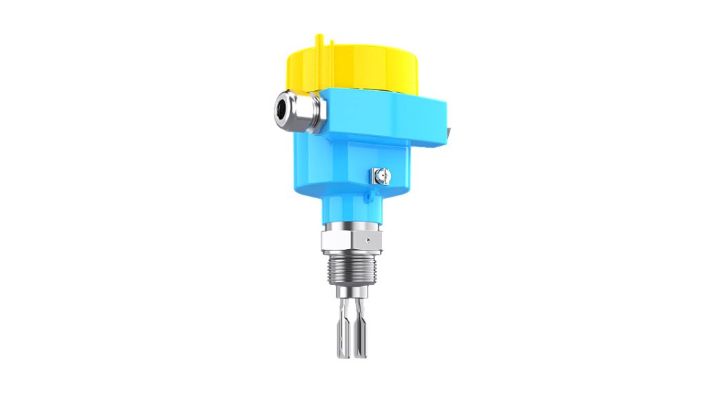
Take the Jiwei Ring-11 tuning fork level switch as an example.
A tuning fork level switch uses piezoelectric elements to drive the fork at its mechanical resonant frequency.
When the tuning fork comes into contact with liquid, its vibration characteristics and resonant frequency change. The internal electronic circuit detects this change and converts it into a switching output.
The process can be summarized as:
Level changes → tuning fork vibration changes → electronic circuit detects the change → output status switches
Although a level switch is also used to detect the level of a material, it does not continuously tell the control system the exact level.
Instead, it answers a much simpler question:
Has the material reached the specified point or not?
This is one of the fundamental differences between a level meter and a level switch.
Jiwei provides a range of level measurement and point level detection instruments, including radar level meters, ultrasonic level meters, magnetic level gauges, float level indicators, tuning fork level switches, tuning fork level switches for solids, vibrating rod level switches, rotary paddle level switches, and RF admittance level switches.
These products are designed for different continuous level measurement and point level detection applications.
5. What Is the Difference Between Analog Signals and Switching Signals?
If we compare an industrial automation system to a person, an analog signal is similar to seeing an exact numerical value, while a switching signal is more like making a yes-or-no judgment based on that value.
For example:
An analog signal tells the PLC:
“The tank level is currently 63%.”
A switching signal tells the PLC:
“The tank has reached the high-level alarm point.”
An analog signal may tell the system:
“The current temperature is 86°C.”
A switching signal may tell the system:
“The high-temperature switch has been activated.”
An analog signal may report:
“The pipeline pressure is currently 0.62 MPa.”
A switching signal may report:
“The pressure switch has changed state.”
Therefore, the fundamental difference between analog signals and switching signals can be summarized as follows:
Analog signals represent continuously changing values, while switching signals represent operating states.
In PLC systems, the abbreviations AI, AO, DI, and DO are frequently used:
AI – Analog Input
Used by the PLC to receive an analog signal from a field instrument.
AO – Analog Output
Used by the PLC or controller to output a continuously variable control signal.
DI – Digital Input
Used to receive digital or switching status signals.
DO – Digital Output
Used to send ON/OFF control commands to field devices.
For example, a radar level transmitter with a 4–20 mA output is usually connected to an AI module of the PLC.
A relay contact from a level switch, on the other hand, is typically connected to a DI module.
6. Why Is a Relay Output Considered a Switching Signal?
Relay outputs are widely used in industrial level switches and point level detection instruments.
From the perspective of a control system, relay contacts mainly have two states:
Open or closed.
For this reason, a relay output is a typical switching signal.
Many Jiwei level switches provide relay output options that can be connected to PLCs, alarm systems, control panels, or interlock circuits through normally open or normally closed contacts.
When the material reaches the specified detection point, the relay changes state, allowing the control system to respond accordingly.
Consider a high-level protection system for a storage tank.
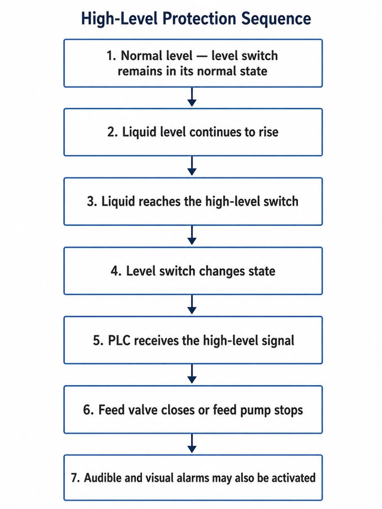
In this application, the control system does not necessarily need to know the exact liquid level.
The key information is simply:
Has the liquid reached the dangerous high-level point?
Therefore, a switching signal is ideally suited to this type of alarm and interlock application.
7. Are Two-Wire, NAMUR, NPN, and PNP Outputs Also Switching Signals?
One important point is that a switching signal does not necessarily mean a mechanical relay contact.
Industrial level switches can use several different electrical output methods, including:
- Relay output
- Two-wire electronic output
- NAMUR output
- NPN transistor output
- PNP transistor output
For example, Jiwei Ring-series tuning fork level switches can be configured with different output options depending on the application and control system requirements.
A NAMUR output uses defined current states to indicate switch status.
NPN and PNP outputs use semiconductor transistor circuits to represent switching states.
Therefore, when determining whether an industrial signal is an analog signal or a switching signal, you should not simply ask:
“Is there current flowing?”
The more important question is:
Does the signal represent a continuously changing measured value, or does it represent one of several defined states?
For example, a 4–20 mA level transmitter changes its current output continuously according to the actual liquid level.
It is therefore an analog signal.
A NAMUR level switch may also use different current values, but those values represent a limited number of conditions such as normal, alarm, or fault.
Its fundamental function is still switching or status detection.
Understanding this difference is particularly important when selecting instruments and configuring PLC input modules.
8. Can Analog Signals and Switching Signals Be Used Together?
Yes. In fact, using both is very common in industrial process applications.
Consider a large chemical storage tank.
The operator may need continuous information about the liquid level for process monitoring, while the plant also requires independent high-high level protection for safety purposes.
A typical solution is:
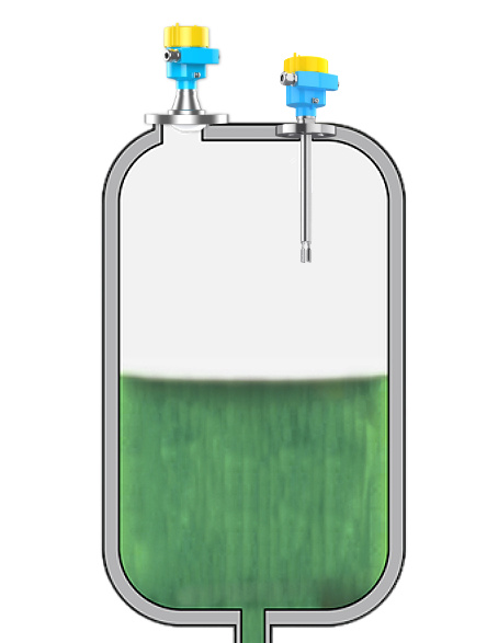
Radar Level Meter + Tuning Fork Level Switch
The radar level meter performs continuous measurement and transmits the real-time level to the DCS through a 4–20 mA signal.
Operators can then monitor information such as:
- Current liquid level
- Percentage of tank capacity
- Level trends
- Historical measurement curves
- Process changes over time
At the same time, an independent level switch can be installed at a critical high-level point.
When the liquid physically reaches that point, the level switch sends a switching signal directly to the alarm or interlock system.
The result is:
Analog signal for continuous monitoring + switching signal for critical point protection
The two technologies are therefore not necessarily alternatives.
In many industrial applications, they complement each other.
For storage tanks, chemical processing systems, pump protection applications, and other critical installations, an independent point level switch can also reduce excessive dependence on a single continuous level measuring instrument.
9. Should You Choose an Analog Signal or a Switching Signal for Level Measurement?
The first step in instrument selection is to determine exactly what information the control system needs.
1. When You Need to Know the Actual Level Continuously
Typical applications include:
- Storage tank inventory monitoring
- Continuous water tank level measurement
- Remote tank farm monitoring
- Level trend analysis
- Automatic process control
- Continuous filling and discharge monitoring
In these applications, a continuous level measuring instrument such as a radar level meter or ultrasonic level meter is generally more suitable.
The instrument can transmit the measurement to the control system using a 4–20 mA analog output or another communication method.
2. When You Only Need to Know Whether Material Has Reached a Certain Point
Typical applications include:
- High-level alarm
- Low-level alarm
- Overflow prevention
- Pump dry-run protection
- Silo full alarm
- Silo empty or low-material alarm
- Equipment interlock
- Automatic start/stop control
In these situations, a level switch or point level switch is often the more appropriate solution.
Depending on the control system, the instrument may use relay, NAMUR, NPN, PNP, or another switching output.
3. When You Need Both Continuous Measurement and Safety Interlocking
For important storage tanks and process equipment, both types of instruments can be installed.
For example, a Jiwei JWrada® radar level meter can be used for continuous level measurement, while a Ring-series tuning fork level switch can provide an independent high- or low-level alarm.
This creates a measurement solution that combines:
Continuous process monitoring with independent point level protection.
10. What Else Should Be Considered When Selecting Analog and Switching Outputs?
Understanding the difference between analog and switching signals is only the first step in instrument selection.
In real industrial applications, several other factors must also be considered.
Check the PLC or DCS Input Type
First, confirm which signal types the PLC or DCS can accept.
If the control cabinet is equipped with 4–20 mA analog input modules, the field transmitter must provide a compatible output.
If a relay contact is used, the digital input circuit and electrical ratings must also be checked.
Signal compatibility between the field instrument and control system is essential.
Consider Transmission Distance and Electrical Interference
Industrial plants often contain:
- Variable-frequency drives
- Electric motors
- High-power cables
- Pumps
- Large electrical equipment
- Electromagnetic interference sources
Cable routing, shielding, grounding, signal type, and installation practices can all affect signal reliability.
This is one reason 4–20 mA current loops remain widely used in industrial process measurement.
Consider Process Conditions
Instrument selection should also take the actual operating conditions into account, including:
- Medium characteristics
- Temperature
- Pressure
- Corrosion
- Viscosity
- Density
- Foam
- Dust
- Build-up
- Installation space
- Vessel geometry
A signal type alone cannot determine whether an instrument is suitable for an application.
Consider Explosion Protection and Safety Requirements
In industries such as oil and gas, petrochemical processing, chemicals, power generation, and applications involving combustible dust, instrumentation may be installed in hazardous areas.
In these environments, instrument selection must also consider requirements such as:
- Explosion-proof certification
- Intrinsic safety
- Enclosure protection
- Electrical connection requirements
- Functional safety requirements
- Environmental conditions
Therefore, selecting between an analog output and a switching output should always be part of a broader instrument selection process.
Jiwei provides level measurement and point level detection instruments for liquids, powders, and granular solids, with applications in industries including chemical processing, power generation, environmental protection, food processing, pharmaceuticals, and building materials.
11. The Simplest Way to Remember Analog Signals vs. Switching Signals
If you still find it difficult to distinguish between analog and switching signals, remember these two sentences:
An analog signal answers the question: “How much?”
A switching signal answers the question: “Has it happened?”
For example, a radar level meter tells the control system:
“The liquid level is currently 6.5 meters.”
That is an analog measurement.
A tuning fork level switch tells the control system:
“The liquid has reached the high-level point.”
That is a switching signal.
Both signal types play important roles in modern industrial automation.
Analog signals are particularly suitable for:
- Continuous measurement
- Process monitoring
- Trend analysis
- Closed-loop control
- Inventory monitoring
Switching signals are particularly suitable for:
- Alarm functions
- Interlocks
- Equipment start/stop control
- High-level protection
- Low-level protection
- Overflow prevention
- Pump protection
Understanding the difference between analog signals and switching signals helps engineers select the correct level meter, level switch, PLC input module, and control architecture.
More importantly, the question should not simply be:
“Which is better, an analog signal or a switching signal?”
Instead, the correct question is:
“Does the application require continuous measurement or point level detection?”
Once this has been determined, engineers can evaluate additional factors such as process medium, temperature, pressure, installation conditions, hazardous-area requirements, output signal compatibility, and PLC/DCS interfaces.
By matching the measurement technology and signal type to the actual process requirements, industrial plants can achieve more stable, reliable, and efficient level measurement and control.
SEO Title
Analog Signals vs. Switching Signals: What’s the Difference in Industrial Automation?
Meta Description
What is the difference between analog and switching signals? Learn how 4–20 mA, relay outputs, PLC I/O, radar level meters, and level switches work in industrial automation and level measurement applications.
Recommended SEO Keywords
Primary keywords: analog signal, switching signal, analog vs switching signal, 4–20 mA signal, industrial instrumentation, level meter, level switch
Secondary keywords: 4–20 mA analog signal, relay output, PLC analog input, PLC digital input, radar level meter, tuning fork level switch, continuous level measurement, point level detection
Long-tail keywords:
- What is the difference between analog and switching signals?
- Is 4–20 mA an analog or digital signal?
- Is a level switch analog or digital?
- Analog input vs digital input in PLC
- Difference between level meter and level switch
- 4–20 mA level transmitter working principle

