
What Is a Transmitter Power Supply?
In industrial automation, level measurement devices such as radar level transmitters, ultrasonic level transmitters, hydrostatic level transmitters, magnetostrictive level sensors, and differential pressure transmitters require a reliable power source to operate correctly.
A transmitter power supply provides the electrical power required by a field transmitter. Depending on the system design, it may also perform additional functions such as signal isolation, 4-20mA signal transmission, intrinsic safety isolation, and HART communication.
Although the power supply does not directly measure the liquid or solid level, it plays an important role in the reliability of the entire measurement loop.
An unstable or incorrectly designed power supply can cause problems such as:
- Unstable level readings
- 4-20mA signal fluctuations
- Failure of the transmitter to start
- Intermittent HART communication
- Incorrect PLC or DCS readings
- Unexpected transmitter restarts
- Signal loss near full-scale output
- Damage caused by surge or lightning events
For this reason, power supply requirements should be considered during the selection of a level transmitter, together with measuring range, process temperature, pressure, medium properties, process connection, and hazardous-area requirements.
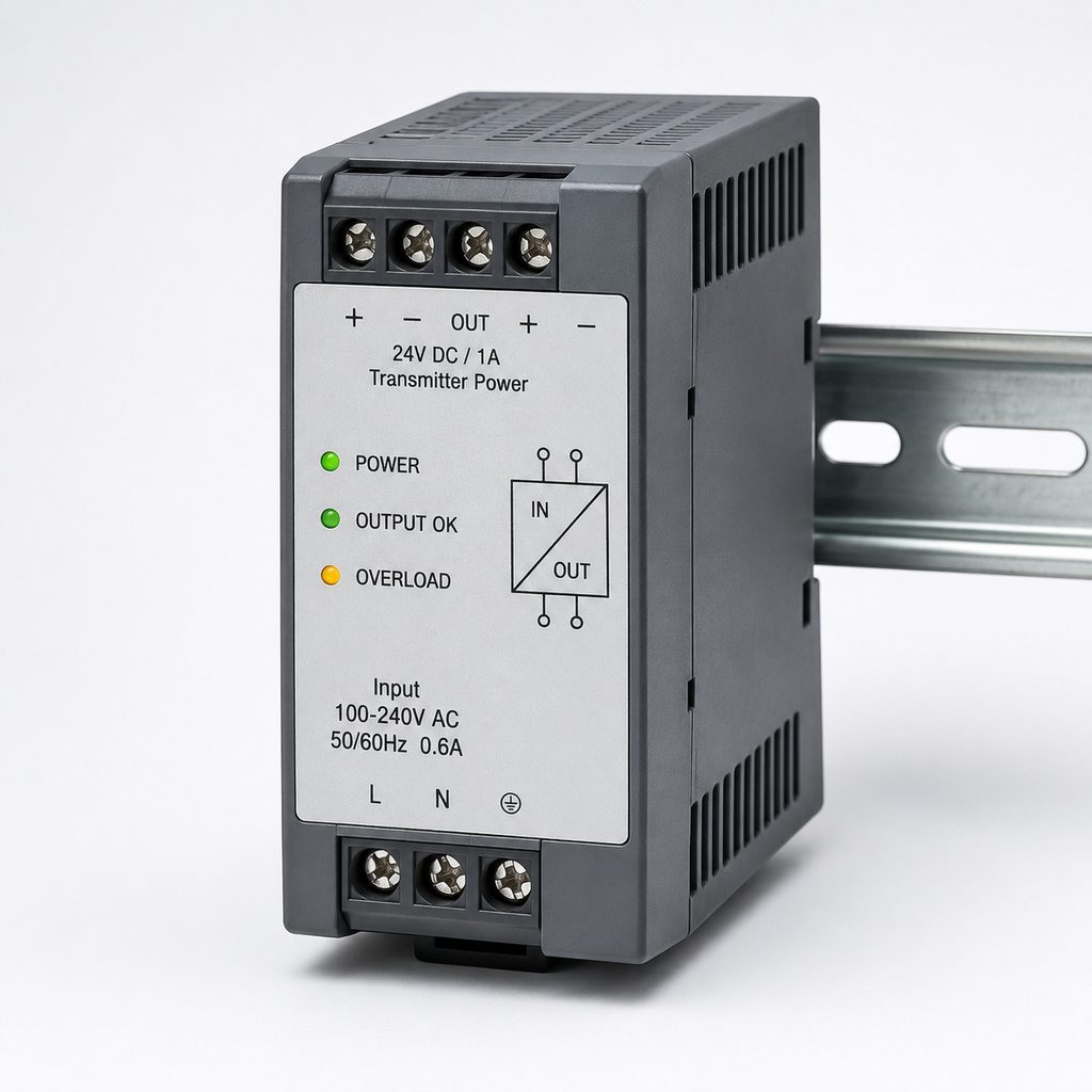
Why Do Level Transmitters Commonly Use 24V DC?
24V DC is one of the most widely used power supply standards in industrial instrumentation and automation systems.
However, it is important to understand that a transmitter labeled for 24V DC operation does not necessarily require exactly 24.00 volts at all times.
Each transmitter has a specified operating voltage range. The acceptable voltage depends on the manufacturer, transmitter design, communication protocol, output type, and hazardous-area certification.
Therefore, the manufacturer’s technical datasheet should always be checked before designing the power supply circuit.
Many industrial level instruments use a two-wire 4-20mA loop. In this configuration, the same pair of wires carries both electrical power and the measurement signal.
The transmitter measures the liquid level, material level, interface, or distance and converts the measured value into a standard 4-20mA current signal. The signal is then received by a PLC, DCS, remote I/O module, display unit, or process controller.
Why Is 24V DC So Common?
There are several reasons.
First, 24V DC is well suited to modern low-power industrial transmitters. Radar sensors, pressure transmitters, temperature transmitters, and other smart field devices can often operate efficiently from a standard 24V control system.
Second, it integrates easily with industrial control panels. PLCs, analog input modules, signal isolators, relays, safety barriers, and other control devices commonly operate within 24V DC systems.
Third, it works well with 4-20mA current loops, allowing two-wire transmitters to receive power and transmit the process signal through the same cable pair.
How Does a Two-Wire Level Transmitter Receive Power?
To understand transmitter power supplies, it is useful to understand the basic operation of a two-wire 4-20mA transmitter.
In a typical current loop, the circuit may look like this:
24V DC Power Supply → Level Transmitter → PLC/DCS Analog Input → Power Supply Return
The exact wiring arrangement depends on whether the analog input is active or passive, but the basic principle remains the same.
The power supply drives the loop while the level transmitter regulates the current according to the measured process value.
For example, if a tank has a measuring range of 0 to 10 meters, the transmitter may be configured as:
- 0 meters = 4mA
- 5 meters = 12mA
- 10 meters = 20mA
The PLC or DCS converts the measured loop current into the corresponding level value.
This type of system offers several advantages:
- Fewer cables
- Simple installation
- Reliable long-distance signal transmission
- Lower wiring costs
- Easy integration with industrial control systems
- Good compatibility with hazardous-area installations
Two-wire technology is therefore widely used for radar level transmitters, pressure-based level transmitters, and many other industrial field instruments.
Two-Wire vs. Four-Wire Level Transmitters
Industrial level measurement devices are commonly available in either two-wire or four-wire configurations.
Understanding the difference is important when selecting the correct transmitter power supply.
Two-Wire Level Transmitters
A two-wire transmitter uses the same two conductors for both power and signal transmission.
The most common configuration is a loop-powered 4-20mA transmitter.
Key advantages include:
- Simple wiring
- Low power consumption
- Reduced cable requirements
- Suitable for long-distance transmission
- Good compatibility with intrinsic safety systems
- Easy connection to PLC and DCS systems
Two-wire designs are commonly found in chemical plants, oil and gas facilities, water treatment systems, food processing plants, pharmaceutical production, and storage tank applications.
Four-Wire Level Transmitters
A four-wire transmitter separates its power supply wiring from its signal output wiring.
For example:
- Two wires may provide AC or DC power
- Two additional wires may provide the 4-20mA output
Four-wire designs are often used when the instrument requires more electrical power or includes additional functions that cannot be supported by a low-power current loop.
Before purchasing a level transmitter, always confirm whether it is:
two-wire loop-powered, four-wire powered, or another configuration.
Incorrect wiring or power supply selection may prevent the instrument from operating correctly and can potentially damage the transmitter.
Why Is a 24V DC Power Supply Not Always Enough?
One of the most common mistakes in industrial instrumentation is assuming that any 24V DC power supply can operate any 24V level transmitter.
In reality, engineers must consider the available loop voltage.
The full output voltage from the power supply is not necessarily available at the transmitter terminals.
Other devices in the current loop may create voltage drops, including:
- PLC or DCS analog input modules
- Intrinsic safety barriers
- Galvanic isolators
- Signal conditioners
- Local indicators
- Long signal cables
- Surge protection devices
The basic design principle can be expressed as:
Power Supply Voltage = Minimum Transmitter Operating Voltage + Total Loop Voltage Drop + Design Margin
Consider a system containing:
24V DC Power Supply → Intrinsic Safety Barrier → Radar Level Transmitter → PLC Analog Input
If the safety barrier, analog input resistance, and cable resistance consume too much voltage, the actual voltage available at the radar level transmitter may fall below its required operating voltage.
This can produce intermittent and confusing problems.
For example, the transmitter may work correctly at a low output current but become unstable as the current approaches 20mA.
Possible symptoms include:
- Normal operation at low levels
- Signal loss at high levels
- Problems above 16mA
- Intermittent HART communication
- Repeated device restarts
- Unstable PLC readings
- Unexpected current-loop faults
Therefore, when selecting a transmitter power supply for a 4-20mA level measurement loop, engineers must consider the entire loop resistance and voltage budget.
Transmitter Power Supply, Signal Isolator, and Safety Barrier: What Is the Difference?
Several components are commonly used in industrial instrumentation systems, including:
- Instrument power supplies
- Transmitter power supplies
- Signal isolators
- Power conditioners
- Intrinsic safety barriers
- Galvanic isolators
Although some products combine several of these functions, they are not necessarily the same device.
Instrument Power Supply
A standard instrument power supply primarily converts an incoming electrical source into a stable DC voltage.
For example, it may convert AC mains power into 24V DC for use by PLCs, transmitters, relays, and other instrumentation equipment.
Transmitter Power Supply
A transmitter power supply may provide power directly to a two-wire field transmitter while also transferring the 4-20mA measurement signal to the control system.
Some transmitter power supplies also provide galvanic isolation or signal conditioning.
Signal Isolator
A signal isolator provides electrical separation between different parts of an automation system.
Its purpose is often to reduce problems caused by:
- Ground loops
- Common-mode voltage
- Electrical interference
- Different ground potentials
- Noise from motors and variable frequency drives
Signal isolation can improve the reliability of analog measurement systems, particularly in large industrial plants.
Intrinsic Safety Barrier
When a level transmitter is installed in a potentially explosive atmosphere, the electrical circuit may require intrinsic safety protection.
An intrinsic safety barrier or galvanic isolator limits the electrical energy that can enter the hazardous area.
This is particularly relevant in industries such as:
- Oil and gas
- Petrochemical processing
- Chemical manufacturing
- Solvent storage
- Fuel terminals
A standard 24V DC power supply should not automatically be considered a substitute for an approved intrinsic safety barrier.
Hazardous-area installations must comply with the applicable equipment certification, control drawings, electrical standards, and project safety requirements.
What Power Supply Is Required for a HART Level Transmitter?
Many modern radar level transmitters and smart level sensors use 4-20mA with HART communication.
HART technology allows the traditional analog current signal to be combined with digital communication.
This means the control system or configuration tool may access additional information such as:
- Measured level
- Distance
- Sensor temperature
- Echo information
- Device status
- Diagnostic alarms
- Measuring range
- Damping settings
- Device identification
- Configuration parameters
If HART communication is required, engineers must consider more than just the power supply voltage.
Every device installed in the loop should be checked for HART compatibility.
A signal isolator or barrier may successfully pass the 4-20mA analog signal but interfere with or block HART digital communication if it is not designed for HART applications.
For this reason, transmitter power supplies, signal conditioners, and safety barriers used in HART systems should be specifically rated for HART-transparent communication when required.
The total loop resistance should also meet the communication requirements specified for the HART system and field device.
How to Select a Transmitter Power Supply for Level Measurement
When selecting a power supply for a radar level transmitter, ultrasonic level sensor, hydrostatic level transmitter, or other industrial level measurement device, several factors should be reviewed.
1. Check the Transmitter Input Voltage Range
Do not rely only on a nominal “24V DC” marking.
Check the manufacturer’s datasheet for the actual minimum and maximum operating voltage.
This becomes especially important when additional devices are installed in series with the transmitter.
2. Confirm Whether the Transmitter Is Two-Wire or Four-Wire
The wiring and power requirements of a two-wire loop-powered transmitter are very different from those of a four-wire instrument.
Always confirm the exact electrical configuration before installation.
3. Calculate the 4-20mA Loop Load
The voltage budget should account for all components in the loop, including:
- Cable resistance
- PLC analog input resistance
- DCS input resistance
- Intrinsic safety barrier voltage drop
- Signal isolator voltage drop
- Local display resistance
- Surge protection devices
- Other series-connected equipment
Cable resistance becomes especially important when the level transmitter is installed far from the control room.
4. Check Power Supply Capacity
If one 24V DC power supply operates multiple radar level transmitters, pressure transmitters, temperature transmitters, and other devices, calculate the total required current.
A reasonable design margin should also be included.
Operating a power supply continuously at its maximum rated load is generally not recommended for a reliable industrial system.
5. Determine Whether Galvanic Isolation Is Required
Industrial sites often contain significant sources of electrical noise, including:
- Variable frequency drives
- Large electric motors
- Solenoid valves
- High-voltage cables
- Heating systems
- Switching power equipment
Proper grounding, shielding, and galvanic isolation can help improve the stability of 4-20mA measurement loops.
6. Check Hazardous-Area Requirements
Level transmitters installed in hazardous areas may require certified intrinsic safety barriers, galvanic isolators, or explosion-protected electrical systems.
The correct solution depends on the transmitter certification and the hazardous-area classification of the installation.
7. Consider Surge and Lightning Protection
Radar level transmitters are frequently installed outdoors on the top of large storage tanks.
These locations can be exposed to lightning-induced surges and electrical transients.
In applications with significant lightning exposure, engineers should consider the complete protection system, including:
- Power supply protection
- Signal-line surge protection
- Cable shielding
- Grounding
- Equipotential bonding
- Proper installation practices
Protecting only the control cabinet may not be sufficient.
Can Power Supply Problems Cause Unstable Level Readings?
Yes.
When a level transmitter produces unstable or fluctuating readings, engineers often suspect the sensor, radar antenna, ultrasonic transducer, or process conditions first.
However, the power supply and signal loop should also be checked.
A practical troubleshooting procedure includes the following steps.
Step 1: Measure Voltage at the Transmitter Terminals
Measure the actual voltage directly at the field transmitter.
Do not assume that the voltage measured at the control cabinet is the same voltage available at the instrument.
Step 2: Measure the 4-20mA Loop Current
Check whether the actual current corresponds to the local transmitter display or expected process value.
Step 3: Check the Total Loop Load
Review recently added components such as:
- Signal isolators
- Safety barriers
- Local indicators
- PLC input modules
- Surge protection devices
Any new component can reduce the available loop voltage.
Step 4: Check Shielding and Grounding
Incorrect grounding can create ground loops and introduce electrical interference into analog signals.
The recommended grounding and shielding method should follow the instrument manufacturer’s installation instructions and the project’s electrical design.
Step 5: Check Power Supply Stability
Look for:
- Voltage fluctuations
- Excessive ripple
- Temporary voltage drops
- Overloaded power supplies
- Intermittent connections
Step 6: Check Nearby Sources of Electrical Interference
Possible sources include large motors, VFDs, contactors, high-voltage equipment, electric heaters, and power cables.
This troubleshooting approach can prevent unnecessary replacement of a level transmitter when the real problem is located elsewhere in the power or signal loop.
Why the Transmitter Power Supply Matters in a Level Measurement System
A radar level transmitter may be the most visible component in a tank measurement application, but reliable measurement depends on the entire instrumentation loop.
A complete system may include:
Level Sensor + Transmitter + 24V DC Power Supply + 4-20mA/HART Signal + Signal Isolator + PLC/DCS + Grounding + Surge Protection
Each component affects overall system performance.
During the level transmitter selection process, engineers should therefore consider:
- Operating voltage
- Two-wire or four-wire configuration
- 4-20mA output
- HART communication
- Loop resistance
- Available voltage
- Signal isolation
- Hazardous-area requirements
- Surge protection
- Grounding and shielding
For radar level transmitters, ultrasonic level transmitters, magnetostrictive level sensors, and other industrial level instruments, choosing the correct transmitter power supply is essential for reliable operation.
A properly designed power and signal loop helps ensure stable 4-20mA transmission, reliable HART communication, accurate PLC or DCS readings, and long-term measurement performance.
Frequently Asked Questions About Transmitter Power Supplies
Why Do Level Transmitters Commonly Use 24V DC?
24V DC is widely used in industrial control systems and is compatible with many PLCs, transmitters, signal isolators, and other field devices. However, the actual allowable voltage range depends on the specific transmitter model and should always be confirmed in the manufacturer’s datasheet.
Does a Two-Wire 4-20mA Level Transmitter Need a Separate Signal Cable?
Normally, no. A two-wire loop-powered transmitter uses the same pair of wires for both electrical power and 4-20mA signal transmission.
Why Will a Radar Level Transmitter Not Start Even If the Power Supply Outputs 24V?
The voltage at the transmitter may be lower than the voltage measured at the power supply. Cable resistance, PLC input resistance, signal isolators, and intrinsic safety barriers can all create voltage drops. Measure the voltage directly at the transmitter terminals while the circuit is operating.
Can a HART Level Transmitter Use a Standard 24V DC Power Supply?
A suitable DC power supply may be used if it meets the transmitter’s electrical requirements, but HART communication also depends on the complete loop design. Signal isolators, barriers, input modules, and loop resistance must be compatible with HART communication.
Can an Explosion-Proof or Intrinsically Safe Level Transmitter Be Connected Directly to a Standard 24V Power Supply?
Not necessarily. Hazardous-area installations must follow the transmitter certification, control drawing, area classification, and applicable electrical standards. An intrinsic safety barrier or galvanic isolator may be required.
Can the Power Supply Affect Level Transmitter Accuracy or Stability?
A poorly designed power and signal loop can cause unstable readings, communication problems, signal loss, or transmitter restarts. Stable power, sufficient loop voltage, correct grounding, proper shielding, and appropriate signal isolation all contribute to reliable level measurement.
What Is the Best Power Supply for a Radar Level Transmitter?
There is no single power supply suitable for every radar level transmitter. The correct choice depends on the transmitter’s voltage range, two-wire or four-wire configuration, 4-20mA/HART requirements, loop resistance, hazardous-area classification, isolation requirements, and the number of instruments powered by the system.

