
When discussing radar level transmitters, terms such as “80 GHz radar,” “high measurement accuracy,” “strong interference resistance,” and “small dead zone” are frequently mentioned. However, from the perspective of basic radar principles and real-world industrial applications, one particularly important advantage of high-frequency radar is often overlooked:
With a similar antenna size, a higher-frequency radar can produce a narrower radar beam.
At first glance, beam width may appear to be just another antenna specification. In practice, however, it directly affects the installation flexibility of a radar level transmitter, its ability to avoid internal obstructions, its suitability for small vessels, its performance in bulk solids applications, and the overall quality of the received echo signal under difficult process conditions.
Therefore, to understand why 80 GHz radar level transmitters have become increasingly popular in industrial level measurement, it is not enough to focus only on the fact that the operating frequency is higher.
The more important engineering benefit is that radar energy can be focused more precisely toward the material being measured.

1. What Is the Beam Angle of a Radar Level Transmitter?
A radar level transmitter sends electromagnetic waves from its antenna into a tank, silo, vessel, or other container.
When these waves reach the surface of a liquid, slurry, powder, granule, or other material, part of the radar energy is reflected back toward the antenna. The instrument receives this echo and determines the distance between the antenna and the material surface based on the propagation time or frequency characteristics of the radar signal.
From this distance, the instrument calculates the level.
However, the radar signal does not travel as a perfectly straight geometric line.
After leaving the antenna, radar energy spreads within a certain angular region. This area can be visualized approximately as a cone that becomes wider as the distance from the antenna increases.
One of the most important parameters used to describe this region is the beam angle.
A larger beam angle means the radar signal covers a wider area. A smaller beam angle means the radar energy is more concentrated.
A simple analogy is a flashlight.
A floodlight illuminates a large area, while a spotlight concentrates light into a much smaller area. In radar level measurement, we often do not want the radar to “see” the entire vessel. Instead, we want it to focus primarily on the actual material surface that needs to be measured.
For this reason, in narrow silos, complex tanks, or vessels containing many internal structures, a narrow radar beam can offer significant engineering advantages over a wide beam.
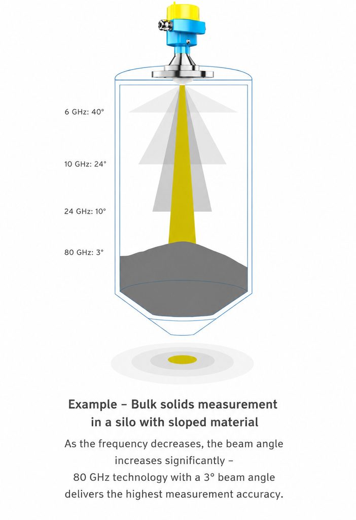
2. Why Can Higher-Frequency Radar Produce a Narrower Beam?
The beam angle of a radar level transmitter is influenced by several factors. Two of the most important are:
Radar operating frequency and effective antenna aperture.
From basic antenna theory, when antenna structure and aperture are comparable, a shorter wavelength generally makes it possible to produce a narrower beam.
And as radar frequency increases, wavelength decreases.
This relationship helps explain the evolution of industrial radar level measurement from lower-frequency radar systems to 26 GHz instruments and, more recently, to approximately 80 GHz radar level transmitters.
Higher-frequency radar makes it possible to use a relatively compact antenna while still producing a highly focused radar beam.
For example, technical information published by Endress+Hauser illustrates this difference clearly. With comparable antenna sizes, an 80 GHz radar can achieve a beam angle of approximately 3°, while a 10 GHz radar may have a beam angle of around 21°.
Other technical documentation on radar level measurement also explains that beam angle is influenced by both antenna size and transmission frequency. Some 80 GHz radar configurations using an approximately 3-inch antenna, for example, can achieve a beam angle of around 3°.
Therefore, the statement that “high-frequency radar has a narrower beam” is not simply a marketing claim. It is based on well-established electromagnetic and antenna principles.
3. Why Is a Narrow Beam So Important in Level Measurement?
To understand the real advantage of high-frequency radar, we need to look at what happens to the radar beam inside an actual tank or silo.
Imagine a radar level transmitter installed on top of a 10-meter-high tank.
The radar beam travels downward from the antenna. As the measuring distance increases, the area covered by the beam gradually becomes larger.
If the beam angle is relatively wide, the radar may cover a substantial area by the time the signal reaches the lower part of the tank.
As a result, many objects inside the vessel can enter the radar’s field of view.
These may include agitator blades, heating coils, reinforcement structures, manways, filling pipes, support beams, vessel walls, ladders, and other internal components.
All of these objects can potentially generate reflections.
For a radar level transmitter, these reflections do not represent the actual product surface. They are unwanted echoes that the instrument must identify, filter, or suppress.
A narrow beam changes this situation significantly.
Engineers can direct the main radar beam toward the liquid or bulk material surface while keeping much of the radar energy away from internal structures.
This reduces unnecessary reflections at the physical level.
In other words, one of the key benefits of a narrow beam is not simply that the software becomes “smarter.”
Instead:
The radar can avoid generating many unwanted echoes in the first place by reducing the number of objects illuminated by the main beam.
This is one reason why high-frequency radar level transmitters can be easier to install and configure in complex vessels.
4. A Narrow Beam Helps Reduce Interference from Tank Walls and Internal Structures
In many radar level measurement applications, the most difficult part of the application is not the process medium itself.
It is the vessel geometry.
Under ideal conditions, there would be a large, unobstructed liquid or material surface directly below the radar antenna.
Real industrial tanks rarely look like this.
In chemical processing, food and beverage, pharmaceutical production, energy, water treatment, and bulk solids handling, vessels may contain a considerable number of internal components.
If a radar level transmitter has a relatively wide beam, some of its energy may strike these structures as the beam expands with distance.
Reflections from internal structures can sometimes be stronger than the reflection from the actual product surface.
The radar transmitter must then rely on echo curve analysis, false-echo suppression, signal processing, and other algorithms to distinguish the true level echo from unwanted reflections.
Modern radar signal-processing algorithms can be extremely sophisticated.
However, from a measurement engineering perspective:
The easiest false echo to process is the false echo that was never generated.
This is where a narrow beam becomes particularly valuable.
An 80 GHz radar level transmitter can concentrate its main energy within a smaller area, making it easier to avoid pipes, baffles, vessel walls, support structures, and other internal obstructions.
This means that part of the interference resistance associated with high-frequency radar comes from advanced signal processing, but another important part comes from simple geometry:
The narrower the beam, the lower the probability that the main radar beam will illuminate an unwanted object.
5. Narrow Beams Are Particularly Useful in Tall, Narrow Silos
Another typical application for narrow-beam radar is the tall and narrow silo.
Silos containing cement, mineral powder, plastic pellets, grain, animal feed, coal, lime, sand, aggregates, and other bulk solids often share a common characteristic:
They can be very tall without being particularly wide.
With a relatively wide radar beam, the coverage area continues to increase as the measuring distance increases.
In a tall silo, this can eventually cause a significant portion of the radar signal to interact with the silo wall.
Once the wall enters the main beam, additional reflections can be created.
High-frequency radar, by contrast, can generate a narrow beam from a relatively compact antenna. This allows more of the radar energy to remain concentrated toward the material surface rather than the surrounding walls.
This characteristic makes high-frequency radar particularly attractive for narrow silos and vessels with limited internal space.
Some 80 GHz radar instruments designed for bulk solids measurement specifically emphasize small beam angles as an advantage for narrow silos and difficult installation conditions.
This benefit becomes even more important in bulk solids applications because, unlike liquids, solid material surfaces are rarely flat.

6. The Value of a Narrow Beam Becomes Even More Important with Uneven Bulk Solid Surfaces
A liquid surface is usually relatively flat when the liquid is at rest.
Bulk solids behave very differently.
Powders, granules, minerals, cement, grain, and similar materials frequently form cones or irregular piles as they enter a silo.
The shape of the surface can also change depending on the filling point, discharge point, material flow characteristics, and operating conditions.
As a result, the radar is not measuring a perfectly horizontal reflective surface.
If the radar beam covers a very large area, the instrument may simultaneously receive reflections from different sections of the material pile, the silo wall, and internal structures.
This creates a more complicated echo environment.
A narrow radar beam helps restrict the main measurement area to a more concentrated region. The instrument can therefore focus more strongly on the selected portion of the material surface.
This does not mean that a narrow beam eliminates every challenge associated with bulk solids measurement.
Material dielectric properties, dust, angle of repose, particle size, signal reflection direction, filling patterns, and radar installation position can all affect measurement performance.
Nevertheless, in many complex bulk solids silos, a narrower beam can significantly increase installation flexibility while reducing unwanted reflections from surrounding structures.
7. Why Can High-Frequency Radar Use a Smaller Antenna?
Beam width has another important advantage that is sometimes overlooked: instrument size.
If a lower-frequency radar needs to produce a very narrow beam, it will generally require a larger effective antenna aperture.
However, industrial plants cannot always accommodate a large horn antenna.
Some tanks and process equipment may only provide relatively small process connections, such as G1, G1½, DN50, or similar openings.
Other applications have limited installation space above the vessel.
In food, pharmaceutical, specialty chemical, and skid-mounted process systems, engineers may also want to minimize the size of components protruding into the vessel.
Because higher-frequency radar operates at a shorter wavelength, it can achieve strong beam focusing with a smaller antenna.
This means engineers do not necessarily have to make the same degree of compromise between antenna size and beam focusing.
Therefore, the development of 80 GHz radar level measurement is about more than simply increasing the operating frequency from 26 GHz to approximately 80 GHz.
One of the more important changes is this:
A compact radar level transmitter can still produce a highly concentrated beam.
This is particularly useful for small tanks, process vessels, reactors, narrow process connections, and skid-mounted equipment.
8. Does a Narrower Beam Always Mean a Better Radar Level Transmitter?
No.
This is an important point when evaluating high-frequency radar technology.
There is no single specification that determines the performance of a radar level transmitter under every process condition.
Operating frequency, beam angle, dynamic range, signal-processing capability, antenna design, dielectric properties of the medium, process temperature, pressure, vapor, foam, dust, condensation, and product buildup on the antenna can all affect measurement performance.
A narrow beam primarily addresses energy focusing and spatial selectivity.
It does not automatically solve every radar measurement problem.
For example, if a radar level transmitter is installed at the wrong location or aimed incorrectly, a very narrow beam may simply focus precisely on the wrong area.
This is particularly important in bulk solids silos, where the material surface can be inclined or highly irregular.
If the installation position and antenna orientation are poorly selected, a narrow beam cannot compensate for incorrect engineering.
Similarly, applications involving severe condensation, extreme foam, heavy buildup, or unusual dielectric properties should be evaluated based on the complete process conditions rather than on operating frequency alone.
A more technically accurate conclusion is therefore:
The narrow beam made possible by high-frequency radar is a major engineering advantage, but it is not the only criterion for evaluating radar level measurement performance.
9. Why Should You Not Compare Radar Level Transmitters Based Only on GHz?
Radar level transmitters are often divided into categories such as “low-frequency radar,” “26 GHz radar,” and “80 GHz radar.”
For engineers selecting an instrument, however, comparing frequency alone is not enough.
Important factors to evaluate include:
- Actual beam angle
- Antenna size and process connection
- Maximum measuring range
- Near-range measurement performance
- Dielectric properties of the medium
- Presence of agitators, heating coils, pipes, or internal structures
- Whether the material is a liquid or bulk solid
- Dust conditions
- Potential antenna buildup or condensation
- Distance between the radar antenna and the vessel wall
- Hazardous-area, SIL, hygienic, or other certification requirements
For example, two radar level transmitters may both operate at approximately 80 GHz, but their actual beam angles and field performance can still differ because of differences in antenna design, antenna aperture, RF architecture, signal processing, and software algorithms.
Therefore, professional radar level transmitter selection should not stop with the question:
“What frequency does this radar use?”
A more useful question is:
“What is the actual beam angle with this specific antenna configuration?”
In many real applications, that question is much closer to the actual engineering challenge.
10. High-Frequency Radar Changes the Way the Instrument “Sees” the Material
If the value of high-frequency radar level measurement had to be summarized in one sentence, it could be expressed like this:
High-frequency radar allows the instrument to look more precisely at the area that actually needs to be measured.
A higher operating frequency means a shorter wavelength. Combined with the appropriate antenna design, this can produce a narrower radar beam.
That narrower beam can then provide several practical benefits: reduced influence from vessel walls, better avoidance of internal obstructions, improved performance in narrow silos, greater installation flexibility, smaller antenna dimensions, and a cleaner echo environment inside complex vessels.
This is why discussions about 80 GHz radar level transmitters should not simply claim:
“Higher frequency means higher accuracy.”
That statement is too simplistic.
In reality, one of the most important advantages of high-frequency radar is not the higher GHz number itself. It is what that higher frequency makes possible: a more focused radar beam.
For the level measurement industry, this distinction matters.
The real challenge in industrial level measurement is not determining which instrument has the largest GHz number.
The real challenge is determining which radar can reliably identify the actual material surface inside a real tank or silo filled with pipes, agitators, dust, uneven material piles, vessel walls, and unwanted reflections.
And a narrow radar beam is one of the most important tools for achieving that goal.
Frequently Asked Questions About High-Frequency Radar and Beam Angle
Why does a high-frequency radar level transmitter have a narrower beam?
With a comparable antenna aperture, a higher radar operating frequency means a shorter wavelength, which generally makes it possible to produce a more concentrated beam. This is why approximately 80 GHz radar level transmitters can achieve relatively small beam angles with compact antennas.
What is the typical beam angle of an 80 GHz radar level transmitter?
There is no single beam angle for all 80 GHz radar transmitters. Beam angle depends not only on operating frequency but also on antenna size and antenna design. Depending on the instrument and antenna configuration, the beam angle may be only a few degrees or considerably wider. Always check the technical specifications for the specific model and antenna.
Is a narrower radar beam always better?
Not necessarily. A narrow beam is particularly useful for narrow vessels, installations with many internal obstructions, and applications where reflections from vessel walls need to be minimized. However, correct installation position, antenna orientation, process conditions, and material characteristics remain equally important.
Is high-frequency radar suitable for bulk solids level measurement?
Yes. High-frequency radar is well suited to many bulk solids applications. A narrow beam can help concentrate the measurement on a selected part of the material surface while reducing interference from silo walls and internal structures.
For this reason, high-frequency radar level transmitters are commonly considered for cement, mineral powder, grain, plastic pellets, coal, lime, aggregates, and other bulk solids. However, dust, material dielectric properties, angle of repose, filling patterns, and installation position should still be evaluated for each application.
What is the main difference between 26 GHz and 80 GHz radar level transmitters?
Neither frequency is automatically better for every application. However, with comparable antenna dimensions, an 80 GHz radar can generally produce a narrower beam than a 26 GHz radar.
This can provide significant advantages in narrow vessels, tanks with complex internal structures, and applications requiring small process connections. Final instrument selection should still consider the medium, measuring range, process conditions, antenna design, and installation environment.
When selecting a radar level transmitter, should I look at frequency or beam angle?
Both matter.
Operating frequency affects several characteristics of the radar system, while beam angle provides a more direct indication of how large an area the radar will illuminate inside the vessel.
For tanks and silos containing agitators, heating coils, pipes, structural components, or nearby vessel walls, beam angle is often one of the most important specifications to evaluate during radar level transmitter selection.

